-

- Sopto Home
-

- Special Topic
-
- Patch Cord Knowledge
-
- Patch Cord Contamination Conditions Sample Images

Patch Cord Knowledge
- Fiber Optic Connector Ferrule Design
- Fiber Optic Connector Design
- E2000 to ST Fiber Patch Cable Overview
- Acceptable and Unacceptable Fiber Connector End-Face Finishes
- Using Wipes and Cleaning Cassettes to Clean Fiber Patch Cords
- Not-Too-Tight Mating of Fiber Optic Connectors
- Matching Gel and Oils Contamination about Fiber Optic Connectors
- The Effect of Improper Use of Fiber Optic Connectors
- Why Fiber Optic Connectors are Fragile?
SOPTO Special Topic
Certificate


Guarantee
Except products belongs to Bargain Shop section, all products are warranted by SOPTO only to purchasers for resale or for use in business or original equipment manufacturer, against defects in workmanship or materials under normal use (consumables, normal tear and wear excluded) for one year after date of purchase from SOPTO, unless otherwise stated...
Return Policies
Defective products will be accepted for exchange, at our discretion, within 14 days from receipt. Buyer might be requested to return the defective products to SOPTO for verification or authorized service location, as SOPTO designated, shipping costs prepaid. .....
Applications
 Fiber Patch Cords have a widely application. Where the need for the optical fiber connection, where you need fiber optic patch cords.
Testing Equipment
FTTX+ LAN
Optical Fiber CATV
Optical Communication System
Telecommunication
SNS Page


SOPTO Products
- Fiber Optic Transceiver Module
- High Speed Cable
- Fiber Optical Cable
- Fiber Optical Patch Cords
- Splitter CWDM DWDM
- PON Solution
- FTTH Box ODF Closure
- PCI-E Network Card
- Network Cables
- Fiber Optical Adapter
- Fiber Optical Attenuator
- Fiber Media Converter
- PDH Multiplexers
- Protocol Converter
- Digital Video Multiplexer
- Fiber Optical Tools
- Compatible
Related Products
Performance Feature
Good Water-proof
Low insertion loss;
low reflection loss;
Stability, good repeatability;
High-precision ceramic ferrule;
Compatible with NTT standard;
Precision Grinding and fully testing;
Compliance with international standards
Patch Cord Knowledge
Recommended

Patch Cord Contamination Conditions Sample Images
These images describe various contamination conditions.
|
Illustration |
Description |
|
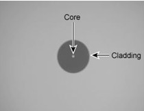
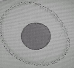
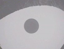
Figure 1: A Clean Connector
|
Figure 1 shows a clean single mode ceramic endface at 200x magnification. Note: Sometimes the core is not illuminated. |
|
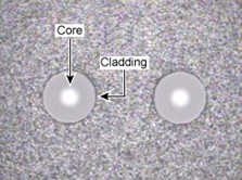
Figure 2: Clean Multifiber Connector with Acceptable Shadowing
|
Figure 2 shows a clean multimode MT connector. Notice that there is a small amount of acceptable shadowing along the edge of the cladding. Note: There is more than one fiber visible at 200x magnification and sometimes the core is not illuminated. |
|
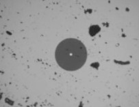
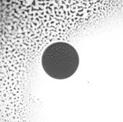
Figure 3: Connector with Dust
|
Figure 3 shows a connector with dust particles spread across the surface of the endface that needs cleaning. |
|
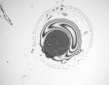
Figure 4: Connector with Liquid Contamination
|
Figure 4 shows a connector with liquid contamination that needs cleaning. |
|
Figure 5: Connector with Liquid Contamination
|
Figure 5 shows a connector with liquid contamination that needs cleaning. |
|
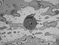
Figure 6: Connector with Alcohol Residue Contamination
|
Figure 6 shows a connector with alcohol residue that needs cleaning. |
|
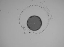
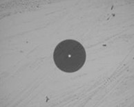
Figure 7: Connector with small droplets of liquid contamination
|
Figure 7 shows a connector with small droplets of liquid contamination that needs cleaning. |
|
Figure 8: Connector with Dry Residue
|
Figure 8 shows a connector with a dry residue that needs cleaning. |
|
Figure 9: Connector with Oil Residue
|
Figure 9 shows a connector with an oil residue that needs cleaning. |
|
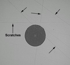
Figure 10: Connector with Scratches
|
Figure 10 shows a connector with scratches. These scratches are not detrimental to the endface and does not clean off. But, deep scratches that appear to cross the fiber-optic core can cause signal loss. |
|
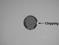
Figure 11: Connector with Chipped Cladding and Excessive Epoxy
|
Figure 11 shows a connector with damage to the cladding. Cleaning cannot remove damaged cladding. A small amount of epoxy around the cladding is allowable, but this shows excessive epoxy around the cladding that does not clean off. This connector must be replaced. |
|
Figure 12: Damaged Connector
|
Figure 12 shows a 1.25 mm ferrule that has been over chamfered. The connector must be replaced. |
Related Knowledge: