-

- Sopto Home
-

- Special Topic
-
- Patch Cord Knowledge
-
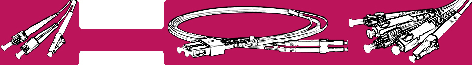
- Fiber Optic Connector Design
Patch Cord Knowledge
- Fiber Optic Connector Ferrule Design
- Fiber Optic Connector Design
- E2000 to ST Fiber Patch Cable Overview
- Acceptable and Unacceptable Fiber Connector End-Face Finishes
- Using Wipes and Cleaning Cassettes to Clean Fiber Patch Cords
- Not-Too-Tight Mating of Fiber Optic Connectors
- Matching Gel and Oils Contamination about Fiber Optic Connectors
- The Effect of Improper Use of Fiber Optic Connectors
- Why Fiber Optic Connectors are Fragile?
SOPTO Special Topic
Certificate


Guarantee
Except products belongs to Bargain Shop section, all products are warranted by SOPTO only to purchasers for resale or for use in business or original equipment manufacturer, against defects in workmanship or materials under normal use (consumables, normal tear and wear excluded) for one year after date of purchase from SOPTO, unless otherwise stated...
Return Policies
Defective products will be accepted for exchange, at our discretion, within 14 days from receipt. Buyer might be requested to return the defective products to SOPTO for verification or authorized service location, as SOPTO designated, shipping costs prepaid. .....
Applications
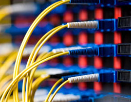 Fiber Patch Cords have a widely application. Where the need for the optical fiber connection, where you need fiber optic patch cords.
Testing Equipment
FTTX+ LAN
Optical Fiber CATV
Optical Communication System
Telecommunication
SNS Page


SOPTO Products
- Fiber Optic Transceiver Module
- High Speed Cable
- Fiber Optical Cable
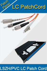
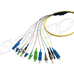
- Fiber Optical Patch Cords
- Splitter CWDM DWDM
- PON Solution
- FTTH Box ODF Closure
- PCI-E Network Card
- Network Cables
- Fiber Optical Adapter
- Fiber Optical Attenuator
- Fiber Media Converter
- PDH Multiplexers
- Protocol Converter
- Digital Video Multiplexer
- Fiber Optical Tools
- Compatible
Related Products
Performance Feature
Good Water-proof
Low insertion loss;
low reflection loss;
Stability, good repeatability;
High-precision ceramic ferrule;
Compatible with NTT standard;
Precision Grinding and fully testing;
Compliance with international standards
Patch Cord Knowledge
Recommended

Fiber Optic Connector Design
The most basic design of demountable connector comprises a ferrule of hole diameter 128–129μm into which the fiber is bonded using an appropriate adhesive as in the figure below. In this most fundamental form the ferrules can be rotated through 360° within an alignment tube or adaptor.
.png)
Connector absolute misalignment
This rotation allows any eccentricity to be fully explored as is discussed below.
In addition a gap of perhaps 5–10μm is incorporated between the ferrule faces. This gap is intended to prevent damage to the fiber ends but has the disadvantage that it incurs both Fresnel loss and loss due to separation effects. Also the gap creates reflections, which limits the achievable return loss to approximately 11dB.
It is worthwhile to review the basic joint losses observed in practice as opposed to those provided in manufacturers’ data, which may have been generated using the interference-fit model or similar distortions. Obviously these losses operate in tandem with losses caused by basic parametric mismatches.
The ferrule hole diameter (FHD) is of considerable importance since the cladding misalignment achieved when jointing a fiber of cladding diameter d1, to another with cladding diameter d2 in an FHD of X will be seen from equation (5.2), in the worst case:
Cladding misalignment = X – (d1 + d2)/2
For a fixed FHD the impact of using fibers with diameters at the lower end of the specified tolerance can be quite severe. For instance, for FHD of 129μm the misalignment for two 122μm fibers can be as much as 7μm, which could result in a power loss of 0.85dB for 50μm core fibers and total loss for single mode fibers.
Two factors work against such losses being encountered. First the specification for cladding diameter is rarely fully explored, with 97% of all fiber lying in the range 123.5–126.5μm. Taking due account of these factors limits the misalignment loss to approximately 3μm, corresponding to a loss of some 0.30dB for a 50μm core fiber. Although this figure is considerably lower than the 1.85dB shown above, it is nevertheless much greater than would be predicted using the interference-fit model (0dB).
Second, the professional termination of the connectors involves filling the ferrule with an adhesive, normally some type of epoxy resin. The fiber is guided through the adhesive and passes through the hole in the ferrule end face. For smaller fibers the adhesive serves to assist in the centralization of the fiber in the hole, thereby reducing the eccentricity.
One of the first optical connectors to be used in data communications was the SMA. This basic demountable connector exhibits random mated worst case insertion losses between 1.3dB and 2.0dB dependent upon the quality of the connector components themselves.
Keyed Connectors
The fact that the ferrules within basic demountable connectors can be rotated through a full 360° implies that the impact of core eccentricity (due to fiber manufacturing tolerance) and cladding-based misalignment (due to fixed FHD) will inevitably surface in the form of rotational variations in insertion loss. This results in poor repeatability.
This undesirable rotational degree of freedom has since led to the introduction of keyed connectors, e.g. keyed or bayonet-mount connectors such as the ST and FC, which define the orientation of the ferrule face against another. This prevents rotation and ensures good repeatability. However, this repeatability is only guaranteed in a given joint since the inherent cladding-based misalignments are still present.
An example would be that ferrule A against ferrule B may achieve 0.5dB insertion loss in a highly repeatable and stable fashion. Also ferrule C against ferrule D may achieve the same performance; however, the difficulty arises when ferrule A is measured against ferrule C or B against D. In these circumstances the insertion loss is unpredictable (but repeatable) although it will lie with the bounds of the limits of the random mated worst case calculation for the joint design.
As a result keyed connectors do not necessarily give better results for insertion loss but are perceived to perform in a more repeatable way; however, this is only true for a given joint.
For more info, please browse our website.