-

- Sopto Home
-

- Special Topic
-
- Patch Cord Knowledge
-
- Fiber Path Cord Production Tools & Procedures & Notes
Patch Cord Knowledge
- Fiber Optic Connector Ferrule Design
- Fiber Optic Connector Design
- E2000 to ST Fiber Patch Cable Overview
- Acceptable and Unacceptable Fiber Connector End-Face Finishes
- Using Wipes and Cleaning Cassettes to Clean Fiber Patch Cords
- Not-Too-Tight Mating of Fiber Optic Connectors
- Matching Gel and Oils Contamination about Fiber Optic Connectors
- The Effect of Improper Use of Fiber Optic Connectors
- Why Fiber Optic Connectors are Fragile?
SOPTO Special Topic
Certificate


Guarantee
Except products belongs to Bargain Shop section, all products are warranted by SOPTO only to purchasers for resale or for use in business or original equipment manufacturer, against defects in workmanship or materials under normal use (consumables, normal tear and wear excluded) for one year after date of purchase from SOPTO, unless otherwise stated...
Return Policies
Defective products will be accepted for exchange, at our discretion, within 14 days from receipt. Buyer might be requested to return the defective products to SOPTO for verification or authorized service location, as SOPTO designated, shipping costs prepaid. .....
Applications
 Fiber Patch Cords have a widely application. Where the need for the optical fiber connection, where you need fiber optic patch cords.
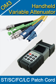
Testing Equipment
FTTX+ LAN
Optical Fiber CATV
Optical Communication System
Telecommunication
SNS Page


SOPTO Products
- Fiber Optic Transceiver Module
- High Speed Cable
- Fiber Optical Cable
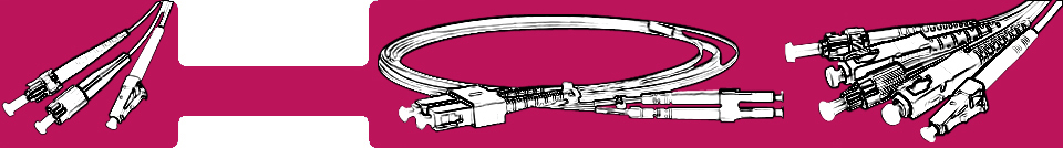
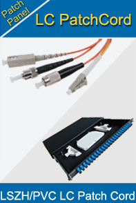
- Fiber Optical Patch Cords
- Splitter CWDM DWDM
- PON Solution
- FTTH Box ODF Closure
- PCI-E Network Card
- Network Cables
- Fiber Optical Adapter
- Fiber Optical Attenuator
- Fiber Media Converter
- PDH Multiplexers
- Protocol Converter
- Digital Video Multiplexer
- Fiber Optical Tools
- Compatible
Related Products
Performance Feature
Good Water-proof
Low insertion loss;
low reflection loss;
Stability, good repeatability;
High-precision ceramic ferrule;
Compatible with NTT standard;
Precision Grinding and fully testing;
Compliance with international standards
Patch Cord Knowledge
Recommended
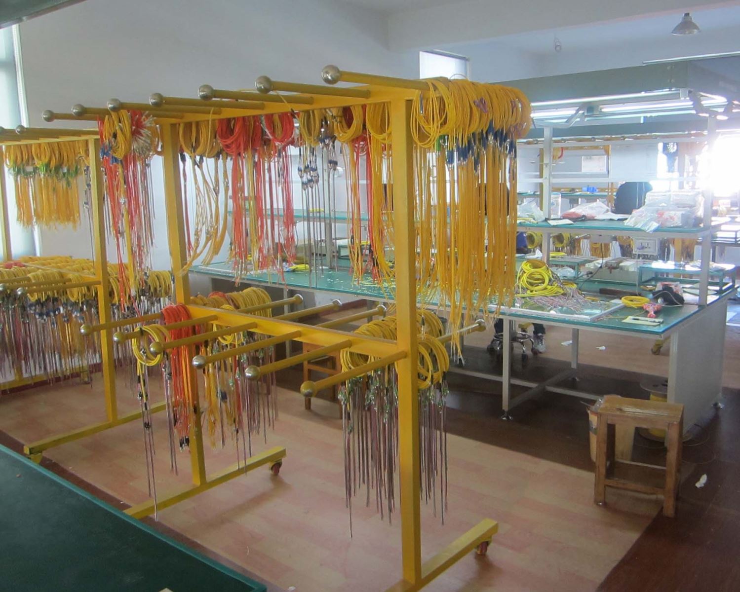
Fiber Path Cord Production Tools & Procedures & Notes
Step 1: Cutting Fiber Cable
Tools Requirement: Automatic cutting machine/a Kevlar cutter
Use Automatic cutting machine or the Kevlar cutter to cut the fiber cable according to the required length of patch cord, then a simple correction.
Step 2: Assemble parts
Assemble various parts to the fiber for the convenience of the subsequent steps.
The sequence to assembling parts is rubber sheath, heat shrinkable tube, pipe and a spring. The direction should pay attention to whether correct.
Step 3: Assign the glue
Tools Requirement: 353nd glue
Evenly assign the Part A and the Part B of the 353nd glue according to the ratio of 10:1 through the auxiliary tool, and minimize bubble.
Step 4: Ferrule
Tools Requirement: stripping pliers, a syringe or dispenser
First, peel off the skin and coating layer of the fiber with fiber stripping pliers. Then, inject the prepared glue into the caudal peduncle of the ferrule by using a syringe or dispenser. Next, penetrate the fiber to the ferrule which has glue, and expose the portion of the optical fiber by hand.
Step 5: Heat curing
Tools Requirement: a curing oven
Bake the ferrule by using a curing oven, until the 353nd glue is completely cured.
Step 6: Remove the glue
Tools Requirement: a cutting knife, a grinding fixture, a sandpaper
First, cut the redundant fiber exposed which is in front of the cured optical fiber head by using a cutting knife. Then, install all the optical fiber heads to the grinding fixture. And then polish the heads with the sandpaper, in order to realize purpose to removing the glue of the ferrule.
Step 7: Polish
Tools Requirement: a grinding machine
Polish the grinding fixture, which has been removed the glue, in the grinding machine. The general process is 9u, 3u, 1u and 0.05u. The grinding time and pressure have a certain relationship with the abrasive paper.
Step 8: Test the end face
Tools Requirement: a detector which can amplify 400 times
Check the grinding effect of end face of the ferrule by using a detector which can amplify 400 times. Generally, the end faces, which have black spots and larger scratch, are unqualified and need to be re-grinded.
Step 9: Assemble the grinded insert-core and parts
Tools Requirement: crimping pliers or a crimping machine
Assemble the ferrule and parts, make them become a connector, and crimp the tail sleeve by using crimping pliers or crimping machine.
Step 10: Test the insertion loss and return loss
Tools Requirement: a insertion and return loss tester
Use the insertion and return loss tester to test the optical fiber connector’s insertion loss and return loss. Generally, we require insertion loss of single mode fibers is less than or equal to 0.3dB. The return loss is greater than or equal to 50dB. The fiber optic patch cords, which need higher requirements, need to do 3D interference test.
Step 11: QA sampling
Quality control personnel spot checks the qualified products, in order to control the quality.
Step 12: Packing
Tools Requirement:bags and labels
Package the qualified products finally.
Notes:
- When assemble parts, the direction should pay attention to whether correct.
- Parts can’t be more or less.
- The fixed parts must be kept tidy on the cable
- Keep the table clean. Parts should be placed in the material box corresponding.
- It should according to the production to produce the quantity of the glue.
- The maximum temperature of the oven should be 97℃~103℃
- The screws on both sides of the oven can’t be screwed too tight in step 5, in order
- If the fiber is broken in the ferrule, we should deal with in time.
Related Knowledge:
- LSZH Material of Fiber Optic Patch Cord
- Guide to Identify Fiber Optic Connectors
- Fiber Patch Cord Connector and Color Codes
- Fiber Connector Ferrule Shapes and Polishes
- Splicing of fiber patch cord
Guess Products You May Like: