-

- Sopto Home
-

- Special Topic
-
- Module Knowledge
-
- Fiber Optic Transceiver Principle
Module Knowledge
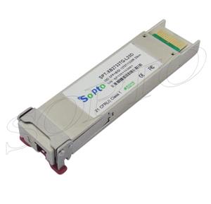
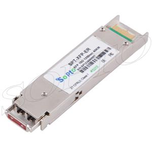
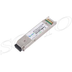
- Tips for Buying 10G XFP Transceivers
- XFP Transceivers for Telecommunications
- Three Types of Ethernet SFP Transceiver Modules Introduction
- Info about High Density CXP Optical Module
- Multipurpose CFP Optical Modules
- Info about CFP Management Interface
- SFP+ Transceivers Short Range Module Overview
- 3 Reasons Every Network Needs GLC-LH-SM Transceiver
- Is the GLC-SX-MM Transceiver Right for Your Switch?
SOPTO Special Topic
Certificate


Guarantee
Except products belongs to Bargain Shop section, all products are warranted by SOPTO only to purchasers for resale or for use in business or original equipment manufacturer, against defects in workmanship or materials under normal use (consumables, normal tear and wear excluded) for one year after date of purchase from SOPTO, unless otherwise stated...
Return Policies
Defective products will be accepted for exchange, at our discretion, within 14 days from receipt. Buyer might be requested to return the defective products to SOPTO for verification or authorized service location, as SOPTO designated, shipping costs prepaid. .....
Applications
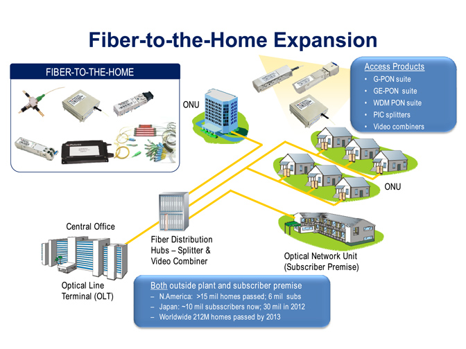 Fiber Optic Transceiver Modules can be applied to these occasions or fields.
Ethernet
IPTV
FTTX
Security
Video Monitor
SDH/SONET
Data Communication
Storage Area Networks
SNS Page


SOPTO Products
- Fiber Optic Transceiver Module
- High Speed Cable
- Fiber Optical Cable
- Fiber Optical Patch Cords
- Splitter CWDM DWDM
- PON Solution
- FTTH Box ODF Closure
- PCI-E Network Card
- Network Cables
- Fiber Optical Adapter
- Fiber Optical Attenuator
- Fiber Media Converter
- PDH Multiplexers
- Protocol Converter
- Digital Video Multiplexer
- Fiber Optical Tools
- Compatible
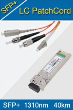
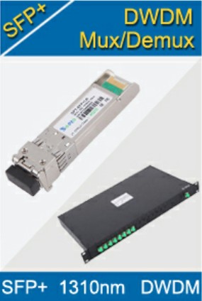
Related Products
 10G SFP+ Transceiver
 40G QSFP+ Transceiver
Performance Feature
Stable
Low cost
Small size
Economic
Dust-proof
High speed
Hot-pluggable
Good EMI, EMC
Wide appliaction field
DDM function available
Long transmission distance
Good Anti-static performance
Module Knowledge
Recommended
Working Principle of a fiber optic transceiver module
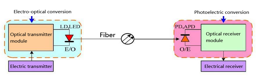
In fiber optic data links, the transmitter converts an electrical signal into an optical signal, which is coupled with a connector and transmitted through a fiber optic cable. The light from the end of the cable is coupled to a receiver, where a detector converts the light back into an electrical signal. Either a light emitting diode (LED) or a laser diode is used as the light source.
As the core of the optical communication devices, Optical transceiver module completes optical signal light - electricity / electricity - light conversion function. Internally can be divided into two separate parts: receive and transmit. The receiving part of the light - electricity conversion to send part of the electrical - optical transform.
Function of fiber optic transceiver module in the optical fiber communication equipment
The function of fiber optical module is to realize the conversion between optical signal and electrical signal (Fiber↔Copper).
Optical transmitter module:
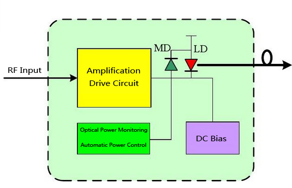
Assembly and Principle of optical transmitter module
The optical transmitter module is composed by the conversion device, which convert the electrical signal with information into the optical signal, and the transmission device, which sends the optical single into the fiber.
Light emitting device -FP-LD, DFB-LD
The FP-LD and DFB-LD are the most commonly used semiconductor light-emitting devices.
Compared with other lasers, LD has advantages of small volume, light weight, low power, large output power, easy modulation, long service life and easy integration and so on.
Laser diode characteristics
LD is a current device. It only emit laser when the Forward Current beyond the threshold current.
In order to make the LD work fast, we must provide the DC bias current IBIAS, which is slightly larger than the threshold current, to the LD.
Two main parameters of LD: Threshold current (Ith) and Slope efficiency (S).
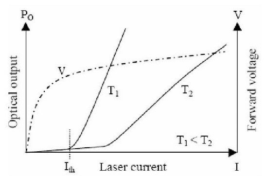
LD temperature characteristics: Temp↑Threshold current ↑, Slope efficiency ↓
In order to keep the output average optical power and extinction, when the temperature is increased, we should increase the IBISA and IMOD.
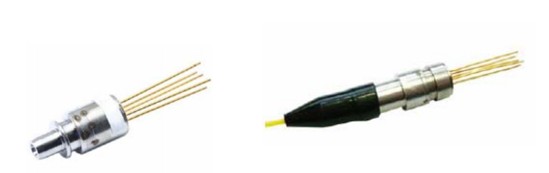
Components of the optical transmitter module (TOSA)
TOSA is main component of the optical transmitter module, in which the light source (semiconductor light emitting diode or a laser diode) is core.
Encapsulate the LD chip, a monitoring photodiode (MD) and other components) in a compact structure (TO coaxial package or butterfly package), then we constitutes the Transmitter Optical Sub-assembly (TOSA).
Laser-diode drive circuit:
Driving circuit is essentially a high-speed current switch
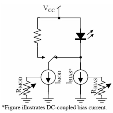
Driving circuit principle
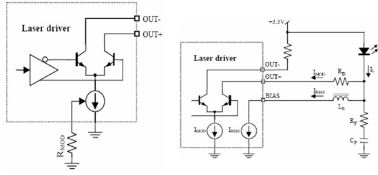
LD modulation current output circuit schematics & LD DC-coupled interface circuit schematics
Laser driving circuit schematics
.jpg)
Driver circuit structure:
A typical laser driving circuit includes the following sections:
1 Differential current switch circuit - output modulation current to the LD
2 The bias current generator - provide a DC bias current to LD
3 Automatic power control (APC) circuit – change IBIAS and keep PAVG Under different temperature and LD aging conditions
4. Fault alarm, the protection circuit
5 Modulate current, bias current monitoring circuit
6 Input shaping circuit (D flip-flop)
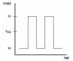
Extinction Ratio:
Definitions of Extinction Ratio (re): re=P1/P0.
P1 is the optical power value of the “1” code;
P0 is the optical power value of the “0” code.
EX=10lg(P1 /P2 )
The Extinction Ratio is a very important indicator of the optical transmitter because it reflects the relative amplitude of the optical signal.
Optical receiver module
The function of the optical receiver module is to converts weak optical signal, which has been transmitted, into the electrical signal and amply.
Optical receiver module principle diagram:
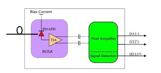
Optical receiving device
The optical receiving device is a photodetector which uses Photoelectric Effect to convert the optical signal into the electrical signal in the communication.
The common photodetector in the fiber optic communication is the PIN photodiode and the avalanche photodiode (APD).
The responsivity of PIN is usually 0.65 ~0.97A/W( λ=0.9 ~1.7μm).
APD is the high sensitivity photodetector which uses the Avalanche Multiplication Effect double the photocurrent so that the receiver sensitivity can be increased 6~10dB.
Preamplifier:
Weak signal current, generated by the photoelectric detector, is converted into a signal voltage of sufficient magnitude by a preamplifier, then output.
In order to suit high data rate application, the preamplifier is composed by a TIA (Trans-Impedance Amplifier).
The Trans-Impedance Amplifier is an I-V converter. The TIA also have AGC functional circuit to ensure enough signal dynamic range.
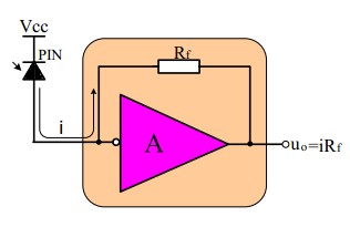
Trans-Impedance Amplifier schematics
Receiver Optical Sub-assembly (ROSA):
In high data rate fiber optical module, it generally assembly the PIN or ADP photodiode and TIA in a hermetically sealed metal enclosure, which becomes the Receiver Optical Sub-Assembly (ROSA).
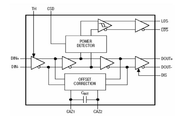
Limiting Amplifier:
The signal output by TIA is the analog signal, which needs to be converted into digital signal before the signal processing circuit can identify it.
The function of Limiting Amplifier is to convert different-amplitude signals into digital signals with same-amplitude.
Limiting Amplifier works and typical circuits:
Limiting Amplifier is mainly composed by three parts, including DC-coupled multi-stage amplifier, DC drift compensation (auto-zero) circuit and Optical power detection alarm circuit.
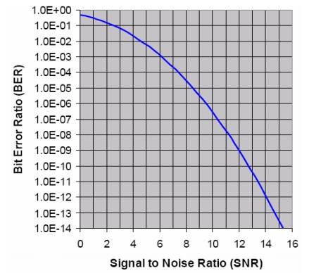
Receiver Sensitivity:
The Receiver Sensitivity refers to the Minimum Average Optical Power which can be received by the Optical Receiver, when the Optical Receiver meets specified bit error rate (BER).
The Receiver Sensitivity is one of the most important indicators of Optical Receiver; and the noise is the most important factor of limiting the Receiver Sensitivity.
As long as we know the TIA Equivalent Input Noise Current, we can calculate the Receiver Sensitivity according to follow diagram.
BER and SNR Relation Graph
Factors which affect the Receiver Sensitivity
- Signal to noise ratio (SNR)
- the extinction ratio of the optical signal
- Transfer rate (data bit rate)
- Jitter
- Signal pattern
- Operating wavelength
- inter-symbol interference
Fiber Optical Transceiver Module
Configuration of Fiber Optical Transceiver Module:
Fiber Optical Transceiver Module = Light Source (Laser) + Driver + Photodetector + Amplifier
![]()
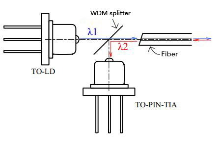
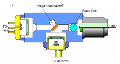
Bi-directional Optical Sub-Assembly (BOSA)
The Bi-directional Optical Sub-Assembly (BOSA) integrates Light Source (FP-LD or DFB-LD), PIN – TIA, splitter, fiber and other components through coaxial coupling process.
You May Want to Know:
You May Like: