-

- Sopto Home
-

- Special Topic
-
- Module Knowledge
-
- How to Install a X2 Transceiver Module?
Module Knowledge
- Tips for Buying 10G XFP Transceivers
- XFP Transceivers for Telecommunications
- Three Types of Ethernet SFP Transceiver Modules Introduction
- Info about High Density CXP Optical Module
- Multipurpose CFP Optical Modules
- Info about CFP Management Interface
- SFP+ Transceivers Short Range Module Overview
- 3 Reasons Every Network Needs GLC-LH-SM Transceiver
- Is the GLC-SX-MM Transceiver Right for Your Switch?
SOPTO Special Topic
Certificate


Guarantee
Except products belongs to Bargain Shop section, all products are warranted by SOPTO only to purchasers for resale or for use in business or original equipment manufacturer, against defects in workmanship or materials under normal use (consumables, normal tear and wear excluded) for one year after date of purchase from SOPTO, unless otherwise stated...
Return Policies
Defective products will be accepted for exchange, at our discretion, within 14 days from receipt. Buyer might be requested to return the defective products to SOPTO for verification or authorized service location, as SOPTO designated, shipping costs prepaid. .....
Applications
 Fiber Optic Transceiver Modules can be applied to these occasions or fields.
Ethernet
IPTV
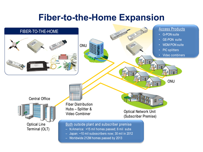
FTTX
Security
Video Monitor
SDH/SONET
Data Communication
Storage Area Networks
SNS Page


SOPTO Products
- Fiber Optic Transceiver Module
- High Speed Cable
- Fiber Optical Cable
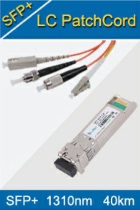
- Fiber Optical Patch Cords
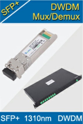
- Splitter CWDM DWDM
- PON Solution
- FTTH Box ODF Closure
- PCI-E Network Card
- Network Cables
- Fiber Optical Adapter
- Fiber Optical Attenuator
- Fiber Media Converter
- PDH Multiplexers
- Protocol Converter
- Digital Video Multiplexer
- Fiber Optical Tools
- Compatible
Related Products
 10G SFP+ Transceiver
 40G QSFP+ Transceiver
Performance Feature
Stable
Low cost
Small size
Economic
Dust-proof
High speed
Hot-pluggable
Good EMI, EMC
Wide appliaction field
DDM function available
Long transmission distance
Good Anti-static performance
Module Knowledge
Recommended
How to Install a X2 Transceiver Module?
The 10-Gigabit Ethernet X2 transceiver module is a hot-swappable I/O device that plugs into 10-Gigabit Ethernet ports. Figure 1 shows an X2 transceiver module with the major features identified. The X2 transceiver module connects the electrical circuitry of the system with the optical or copper network.
Figure 1 10-Gigabit Ethernet X2 Transceiver Module (Optical Version Shown)
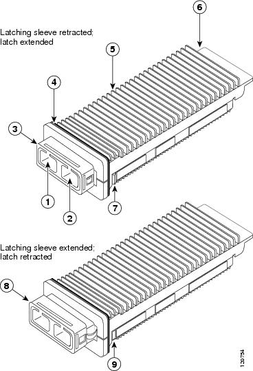
This installation procedure applies to both the spring-loaded and non-spring-loaded X2 transceiver modules.
The X2 transceiver is a static-sensitive device. Always use an ESD wrist strap or similar individual grounding device when handling X2 transceivers or coming into contact with system modules.
10G 1550nm SM X2 ER Transceiver
To install an X2 transceiver module, follow these steps:
Step 1 ![]() Using a small flat-blade screwdriver, carefully pry the X2 transceiver port cover off of the system module faceplate. Use the two arrows on the port cover as guides for inserting the screwdriver blade. Save the port cover for future use.
Using a small flat-blade screwdriver, carefully pry the X2 transceiver port cover off of the system module faceplate. Use the two arrows on the port cover as guides for inserting the screwdriver blade. Save the port cover for future use.
Step 2 Remove the new X2 transceiver module from its protective packaging.
Step 3 Check the label on the X2 transceiver module body to verify that you have the correct model for your network.
Step 4 Remove the dust plug from X2 transceiver module optical port and set it aside.
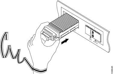
Step 5 Slide the X2 transceiver into the transceiver socket on the system module front panel until the X2 transceiver EMI gasket flange makes contact with the system module faceplate. (See Figure 2.)
Note 10-Gigabit Ethernet X2 transceiver modules are keyed to prevent incorrect insertion.
Figure 2 Installing the 10-Gigabit Ethernet X2 Transceiver Module
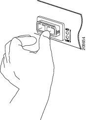
Step 6 Press firmly on the front of the X2 transceiver module with your thumb to fully seat the transceiver in the transceiver socket. (See Figure 3.)
Figure 3 Latching the X2 Transceiver Module
Step 7 Verify that the X2 transceiver is properly seated and latched in the socket, by grasping the left and right sides (or the top and bottom) of the transceiver's EMI gasket flange with your thumb and forefinger and gently pulling on the transceiver. Do not pull on the latching sleeve as you will release the transceiver.
If the transceiver does not pull free, it is properly seated and latched. If the transceiver does pull free, slide the X2 transceiver back into the socket and apply more pressure with your thumb on the front of the transceiver. Repeat the process until the X2 transceiver is securely latched in the socket.
Step 8 Reinstall the dust plug into the transceiver's optical bore until you are ready to attach the network interface cable.
Step 9 If you are cabling an optical X2 transceiver module, follow these sub-steps. If you are cabling a CX4 X2 transceiver module, go to step 10.
a. Remove the dust plugs from the optical network interface cable SC connectors. Save the dust plugs for future use.
b. Inspect and clean the SC connector's fiber-optic end faces.
For complete information on inspecting and cleaning fiber-optic connections, refer to the Inspection and Cleaning Procedures for Fiber-Optic Connections document at Patch Cord Connector General Cleaning Process and Connector Inspection Technique
c. Remove the dust plugs from the X2 transceiver module optical bores.
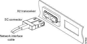
d. Immediately attach the network interface cable SC connectors to the X2 transceiver module. (See Figure 4.)
Figure 4 Cabling an Optical 10-Gigabit Ethernet X2 Transceiver Module
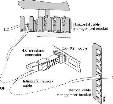
Step 10 Plug the InfiniBand cable connector into the CX4 X2 transceiver module connector. (See Figure 5.) Make sure that the InfiniBand cable connector is aligned with the X2 transceiver module.
Figure 5 Cabling a CX4 (Copper) 10-Gigabit Ethernet X2 Transceiver Module
 10-Gigabit Ethernet X2 Transceiver Module.jpg)
Step 11 Carefully route the InfiniBand network cable through the cable management brackets on your system. Figure 6shows how the InfiniBand cable should be routed through either a horizontal cable management bracket or a vertical cable management bracket.
Note ![]() Make sure that you route the InfiniBand cable through cable management brackets to provide adequate strain relief and cable support when cabling CX4 X2 transceiver modules. The InfiniBand cable is heavy. Without proper support, the InfiniBand cable can cause the cable connector to sag or skew. Misalignment between the cable connector and the transceiver module connector can cause intermittent connections between the cable connector pins and the CX4 X2 transceiver module pins.
Make sure that you route the InfiniBand cable through cable management brackets to provide adequate strain relief and cable support when cabling CX4 X2 transceiver modules. The InfiniBand cable is heavy. Without proper support, the InfiniBand cable can cause the cable connector to sag or skew. Misalignment between the cable connector and the transceiver module connector can cause intermittent connections between the cable connector pins and the CX4 X2 transceiver module pins.
Figure 6 InfiniBand Cable Support
For more high quality fiber optical module, please contact SOPTO.