-

- Sopto Home
-

- Special Topic
-
- Module Knowledge
-
- Experimental Results for the OSA Module and Components Implement
Module Knowledge
- Tips for Buying 10G XFP Transceivers
- XFP Transceivers for Telecommunications
- Three Types of Ethernet SFP Transceiver Modules Introduction
- Info about High Density CXP Optical Module
- Multipurpose CFP Optical Modules
- Info about CFP Management Interface
- SFP+ Transceivers Short Range Module Overview
- 3 Reasons Every Network Needs GLC-LH-SM Transceiver
- Is the GLC-SX-MM Transceiver Right for Your Switch?
SOPTO Special Topic
Certificate


Guarantee
Except products belongs to Bargain Shop section, all products are warranted by SOPTO only to purchasers for resale or for use in business or original equipment manufacturer, against defects in workmanship or materials under normal use (consumables, normal tear and wear excluded) for one year after date of purchase from SOPTO, unless otherwise stated...
Return Policies
Defective products will be accepted for exchange, at our discretion, within 14 days from receipt. Buyer might be requested to return the defective products to SOPTO for verification or authorized service location, as SOPTO designated, shipping costs prepaid. .....
Applications
 Fiber Optic Transceiver Modules can be applied to these occasions or fields.
Ethernet
IPTV
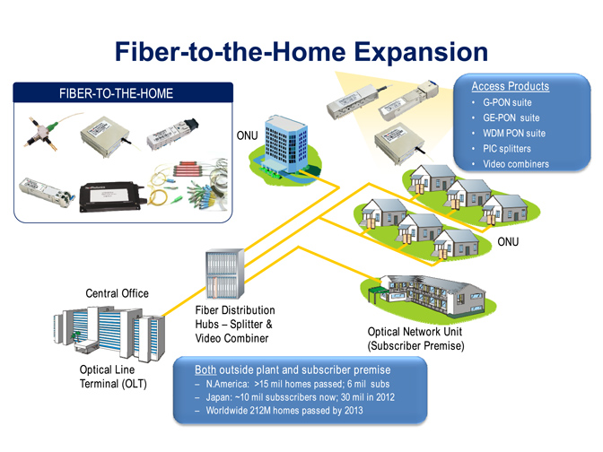
FTTX
Security
Video Monitor
SDH/SONET
Data Communication
Storage Area Networks
SNS Page


SOPTO Products
- Fiber Optic Transceiver Module
- High Speed Cable
- Fiber Optical Cable
- Fiber Optical Patch Cords
- Splitter CWDM DWDM
- PON Solution
- FTTH Box ODF Closure
- PCI-E Network Card
- Network Cables
- Fiber Optical Adapter
- Fiber Optical Attenuator
- Fiber Media Converter
- PDH Multiplexers
- Protocol Converter
- Digital Video Multiplexer
- Fiber Optical Tools
- Compatible
Related Products
 10G SFP+ Transceiver
 40G QSFP+ Transceiver
Performance Feature
Stable
Low cost
Small size
Economic
Dust-proof
High speed
Hot-pluggable
Good EMI, EMC
Wide appliaction field
DDM function available
Long transmission distance
Good Anti-static performance
Module Knowledge
Recommended
Experimental Results for the OSA Module and Components Implementation Part 1
A demonstration system for a four-channel end-to-end bidirectional optical link is shown in Fig. 1
.png)
Figure 1 A demonstration system for a four-channel end-to-end bidirectional optical link
Fig. 1 Photograph of the demonstration system for a four-channel bidirectional optical link with the up-link module (left) and the down link module (right) installed on the same evaluation board: the inset shows a top view of the main board, showing the OSA module with the optical components of the TRx IC board and chips.
To measure the performance of the fabricated bidirectional OSA modules, four-channel evaluation boards were designed with input and output ports to transmit and receive data signals. Two different modules for the up-link to send 850 nm signals and for the down-link to send 1060 nm signals are installed on the same evaluation boards.
These modules were connected using an OM3 standard MMF fibers array with four channels and a length of 2 m to measure the end-to-end optical link. The inset shown in Fig. 1 is a photograph of the main board, including the OSA module with the optical components of the TRx IC board and chips.
The main board is connected to an evaluation board for measurement purposes using a 0.8 mm pitch input/output (I/O) connector. The evaluation board is made of a ceramic board filled hydrocarbon material, which has good electrical and thermal properties .
Demonstration of the bidirectional optical link
To demonstrate the bidirectional optical link, frequency responses and eye-diagrams were measured using the evaluation boards shown in Fig. 1. An Anritsu MP1763B pulse pattern generator and an Agilent 86100A oscilloscope are used to feed input electrical signals and to measure output electrical signals to/from the evaluation boards. This setup measures the electrical-to-electrical responses received by the PD and receiver IC after light signal transmission from the VCSEL and driver IC.
40G 850nm 150m QSFP+ SR4 Fiber Optic Transceiver Module
To measure the responses and eye-diagram separately for each channel, the signal is transmitted through one channel while the other channels are stood as turn-on states without the input of modulated signals. The eye-diagrams were measured using a pseudorandom bit stream of 231-1. Differential splitter-baluns (5320B-104) were utilized to convert single-ended signals to differential signals for the measurement of the BER and crosstalk. The BER and eye-diagrams were measured at 10 Gb/s/ch to demonstrate the 40 Gb/s bidirectional optical link.

Figure 2 The measured frequency responses with the crosstalk of the unidirectional up-link
(a) Crosstalk from Ch1 to other channels
(b) Crosstalk from Ch2 to other channels,
(c) Crosstalk from Ch3 to other channels,
(d) Crosstalk from Ch4 to other channels.
Figure 2 shows the measured frequency response of the four-channel optical link and the crosstalk between the channels for a unidirectional up-link. The signal lines are connected to the Tx/Rx ICs, VCSEL/PD and OSA modules on both Tx/Rx sides. Therefore, the measured frequency response includes the influences from these components. All channels have a uniform gain profile with a stable 3-dB bandwidth with a response of about 7.5 GHz, which is enough for 10 Gb/s/ch data transmission.
The crosstalk measurement includes the parasitic crosstalk from the bidirectional optical link and the signal lines of the TRx IC board, I/O connectors, and evaluation boards. The average crosstalk from Ch1 to the neighboring channels is less than −25.6 dB; that from Ch2 to the neighboring channels is less than −24.1 dB, that from Ch3 to the other channels is less than −22.6 dB, and that from Ch4 to the other channels is less than −25.2 dB.
Hence, the overall crosstalk of the bidirectional optical link from the source to the neighboring channels is less than −22.6 dB. The average crosstalk value was higher than that obtained from a single OSA module, at approximately −45 dB to −50 dB, as the crosstalk measurement was performed with two separate OSA modules attached to the main board and then connected to two evaluation boards. For this reason, crosstalk between the channels occurs due to the electrical and optical signal transmission.
However, it is difficult to extract optical crosstalk from electrical crosstalk. Hence, we measured the crosstalk of the main board (without the OSA module), the I/O connector, and the evaluation board in order to determine the electrical crosstalk between adjacent channels. Average crosstalk ranging from −21 dB to −30 dB was obtained. Thus, the crosstalk contributions of the I/O connector and the evaluation board seriously affect the overall crosstalk measurement of the bidirectional optical link.
.png)
Figure 3 Measured eye-diagrams of the four-channel half-duplex bidirectional optical link at 10 Gb/s/ch
(a) For the up-link (850 nm)
(b) For the down-link (1060 nm), 16.6 ps/div is shown in the diagram.
Figure 3 shows eye-diagrams of the four-channel half-duplex bidirectional optical link measured at 10 Gb/s/ch. In the half-duplex mode, the up- and down-links are separately operated. For example, for the up-link measurement, the transmitter part in the down-link module is turned-off while the receiver part is turned-on. Each channel shows relatively clear and uniform eyes for both the up- and the down-link.
The peak-to-peak jitters for up-link/down-link are less than 28.6/56.0 ps for Ch1, 38.0/41.0 ps for Ch2, 36.8/56.8 ps for Ch3 and 42.7/61.7 ps for Ch4. The measured rise/fall times are less than 31.7/32.5 ps for Ch1, 32.0/30.3 ps for Ch2, 32.9/32.1 for Ch3, and 30.7/27.7 ps for Ch4 for both the up- and the down-link, respectively. The eye-diagram measurement shown in Fig. 3 is the measurement result taken from the optical link including the proposed bidirectional OSA module.
In order to measure the eye-diagrams, a pulse pattern generator generates an electrical voltage signal which is then converted to an optical signal by the Tx IC and VCSEL, and using the bidirectional OSA module on the Tx side, the optical signal is transmitted through the optical fiber.
The optical signal is then passed to the PD by the OSA module located on the Rx side and finally the photocurrent generated by the PD is converted to an electrical voltage signal with the Rx IC to feed to the oscilloscope. Thus, the eye-diagrams are recorded after converting the optical signal back to the electrical signal by the PD and Rx IC. The eye-diagram is recorded for Ch1 when the signal is transmitted only from Ch1 by the Tx IC and VCSEL on the Tx side and received by the Rx IC and PD on the Rx side. Hence, during the recording of the eye-diagram through Ch1, the other channels (Ch2, Ch3, and Ch4) are not transmitting.
Thus, all channels are recorded separately, while the other channels are not transmitting. The down-link with the 1060 nm wavelength has higher jitter compared to the up-link with the 850 nm wavelength. This result may be due to the VCSELs used in the down-link, which has a wider divergence angle and also higher coupling losses, and the effects of the conversion of the signal from electrical to optical and optical to electrical.
.png)
Fig. 4 The BER measurement results of the half-duplex bidirectional optical link at 10 Gb/s/ch
(a) For the up-link (850 nm)
(b) For the down-link (1060 nm).
Figure 4 shows the measured results of the BER versus the input power at 10 Gb/s/ch with the half-duplex bidirectional optical link for the up- and down-link, separately measured. To measure the BER of the optical link with bidirectional OSA modules, fixed MMF attenuators were utilized. The BER performance levels of the four-channel bidirectional optical link showed uniformity within 1.2 dB.
To obtain a BER of less than 10−12 for the up- and the down-link, the received light power should be higher than −8 dBm and −6.5 dBm, respectively. The down-link with the 1060 nm wavelength has higher jitter and requires more received power to obtain a BER of less than 10−12 compared to the up-link with the 850 nm wavelength, this may be due to the higher end-to-end coupling loss at 1060 nm.
Notices: This article is reprinted from: opticsinfobase.org/oe/fulltext.cfm?uri=oe-22-2-1768&id=277085
By the way, Sopto supplies high quality fiber optical modules and fiber optical connectors with reasonable price. For the newest quotes, please contact a Sopto representative by calling 86-755-36946668, or by sending an email to info@sopto.com. For more info, please browse our website.
You May Like: