-

- Sopto Home
-

- Special Topic
-
- Converter Knowledge
-
- What is the Difference between RS232 and RS485 Serial Interfaces
Converter Knowledge
- Form Factors and Application of Ethernet Media Converter
- Ethernet over 4 E1 Converter Brief Introduction
- What is the Difference between RS232 and RS485 Serial Interfaces
- What is the Difference between RS232 and RS485 Serial Interfaces
- How to Convert an Analog Telephone to VoIP Protocol?
- How to Find the Internet Protocol Address and Media Access Contr
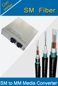
- How to Convert from Fast Ethernet to Fiber Optics?
- How to Connect a Fiber Converter?
- How to Convert Ethernet to Fiber Media Converters?
SOPTO Special Topic
Certificate


Guarantee
Except products belongs to Bargain Shop section, all products are warranted by SOPTO only to purchasers for resale or for use in business or original equipment manufacturer, against defects in workmanship or materials under normal use (consumables, normal tear and wear excluded) for one year after date of purchase from SOPTO, unless otherwise stated...
Return Policies
Defective products will be accepted for exchange, at our discretion, within 14 days from receipt. Buyer might be requested to return the defective products to SOPTO for verification or authorized service location, as SOPTO designated, shipping costs prepaid. .....
Applications
An Ethernet to Fiber Media Converter can also be used where there is high level of electromagnetic interference or EMI which is a common phenomenon found in industrial plants. This interference can cause corruption of data over copper-based ethernet links. Data transmitted over fiber optic cable however is completely immune to this type of noise. An Ethernet to Fiber Optic Converter therefore enables you to inter-connect your copper-ethernet devices over fiber ensuring optimal data transmission across the plant floor.
SNS Page


SOPTO Products
- Fiber Optic Transceiver Module
- High Speed Cable
- Fiber Optical Cable
- Fiber Optical Patch Cords
- Splitter CWDM DWDM
- PON Solution
- FTTH Box ODF Closure
- PCI-E Network Card
- Network Cables
- Fiber Optical Adapter
- Fiber Optical Attenuator
- Fiber Media Converter
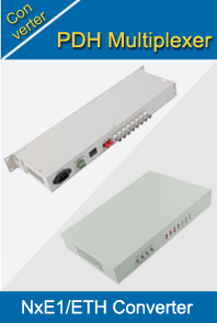
- PDH Multiplexers
- Protocol Converter
- Digital Video Multiplexer
- Fiber Optical Tools
- Compatible
Related Products
Performance Feature
Converter Knowledge
Recommended
What is the Difference between RS232 and RS485 Serial Interfaces Part 1?
Dozens of serial data interfaces are used today. Most have been developed for specific applications. A few have become universal, such as I2C, CAN, LIN, SPI, Flex, MOST, and I2S. Then there’s Ethernet and USB and other higher-speed serial interfaces like FireWire, HDMI, and Thunderbolt. Two of the oldest interfaces are RS232 and RS485. These legacy interfaces aren’t obsolete or discontinued, though. Both are still alive and well in many applications.
Serial Interfaces
The whole purpose of a serial interface is to provide a single path for data transmission wirelessly or over a cable. Parallel buses are still used in some applications. But with high-speed data so common today, a serial interface is the only practical option for communications over any distance greater than several feet.
Serial interfaces can be used to provide standardized logic levels from transmitters to receivers, define the transmission medium and connectors, and specify timing and data rates. In some cases, they can perform serial-to-parallel and parallel-to-serial conversion or specify a basic data protocol.
The definition of logic levels, medium, and connectors is part of the physical layer (PHY) or layer 1 of the Open Systems Interconnection (OSI) networking model. Any additional functions such as data handling is part of the media access control (MAC) layer or layer 2 of the OSI model.
RS232 Introduction
One of the oldest serial interfaces is generically called RS232. It was originally established in 1962 as a method of connecting data terminal equipment (DTE) such as electromechanical teletypewriters to data communications equipment (DCE). Over the years its use has included connections to video terminals, computers, and modems.
The first personal computers included an RS232 called a serial port for connection to a printer or other peripheral device. Today, it is still widely used in embedded computer development systems, scientific instruments, and all sorts of industrial control equipment.
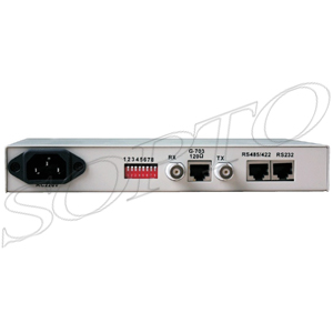
E1 to RS232 RS422 RS485 Protocol Converter
The official name of the standard is Electronic Industries Association/Telecommunications Industries Association EIA/TIA-232-F. The letter F designates the most recent standard modification and update. The standard is essentially the same as the International Telecommunications Union – Telecommunications (ITU-T) specifications V.24 and V.28.
The standard defines a logic 1 and a voltage between –3 and –25 V and a logic 0 as a voltage level between +3 and + 25 V (Fig. 1). Signal levels are commonly referred to as a mark for logic 1 and a space for logic 0. Voltages between ±3 V are invalid, providing a huge noise margin for the interface. Noise voltages in this range are rejected. In common practice, logic 0 and 1 levels are typically as low as ±5 V and as high as ±12 or ±15 V. The transmitter and receiver configurations are single-ended (not differential) with a ground reference.
.png)
Figure 1. Voltage levels define the logic 1 or mark and the logic 0 or space characters. Voltages between ±3 V are invalid.
The cable medium can be simple parallel wires or twisted pair. The length of the cable determines the upper data rate and generally should not exceed 50 feet. However, much longer cable lengths can be used with low data rate conditions. Today the primary goal is to use a cable with no more than 2500 pF of capacitance between wires.
This limits the upper data rate to roughly 20 kbits/s. Because of the low-speed data rates used with this interface, the cable generally isn’t treated as a formal transmission line. Transmission lines require matched generator and load impedances to eliminate reflections that cause data corruption.
The standard defined a 25-pin connector called the DB-25, which was designed to carry a variety of control lines as well as the serial data transmit and receive lines. Such connectors are rarely used today. Instead, a nine-pin connector called the DE-9 was defined, and today it is the de facto standard (Fig. 2).
.png)
Figure 2. The popular DB9 connector carries the signals shown. The numbers are the pin numbers on the connector.
Originally, data rates for electromechanical equipment were very slow. A minimum rate was typically 75 bits/s, but rates of 150 and 300 bits/s were common. Today, data rates are defined by the protocol used with the interface and can range as high as 115.2 kbits/s. Typical data rates are 1200, 2400, 4800, 9600, 19,200, 38,400, and 115,200 bits/s. The data rate is limited by the maximum allowed slew rate of 30 V/µs (volts per microsecond). For short low-capacitance cables, data rates can be as high as several megabits per second with the appropriate drivers.
Many RS-232 connections are one-way or simplex. However, using the special signaling and control voltages available, two-way or half-duplex operation is possible. The two connected devices alternate transmitting and receiving operations.
The control signals in the interface define the protocol for transmitting and receiving data. These signals tell the two communicating devices when they are busy, transmitting, ready, and receiving. The transmitting device is the DTE such as a computer, and the receiving device is the DCE such as a printer. The control signals used on the common nine-pin connector are:
- Data carrier detect (DCD): The DCE tells the DTE it is receiving a valid input signal.
- Data set ready (DSR): The DCE tells the DTE it is connected and ready to receive.
- Received data (RD): This is the actual signal received from the DTE.
- Request to send (RTS): This signal from the DTE tells the DCE it is ready to transmit.
- Transmit data (TD): This is the transmitted signal from the DTE.
- Clear to send (CTS): This line from the DCE tells the DTE it is ready to receive data.
- Data terminal ready (DTR): This line is from the DTE to the DCE indicating readiness to send or receive data.
- Ring indicator (RI): This line was used in older modem connections but isn’t used anymore.
- Signal ground: This is the common ground connection for all signals.
Figure 3 shows the cable connections from the DTE to the DCE. Note the interconnections between the control line pins. The signals on these pins occur in response to one another in what is called a flow control or “handshaking” process.
.png)
Figure 3. This is a common connection between the DTE and the DCE devices. Note the connections in the cable from one connector to the other.
Although not formally part of the RS232 standard, most serial devices using the interface also use what is called a universal asynchronous receiver transmitter (UART). This IC, usually separate from the line driver and receiver circuits, implements a basic communications protocol that involves transmitting up to 8 bits at a time. It performs serial-to-parallel and parallel-to-serial conversion, adding start and stop bits to signal the beginning and end of a data word, parity bit error detection, and establishment of the data rate.
The data is often ASCII characters, but any data word up to 8 bits can be transmitted (Fig. 4). The UART can usually be configured to handle different word sizes (5 to 8 bits), add 1, 1.5, or 2 stop bits, and include odd, even, or no parity bits. Data rates from 75 bits/s to 115.2 kbits/s are selectable.
.png)
Figure 4. EIA/TIA-232 signal for transmitting a 7-bit ASCII capital letter J
This is the EIA/TIA-232 signal for transmitting a 7-bit ASCII capital letter J. A start bit signals the beginning of the character. The LSB is transmitter first. An odd parity bit is included. The transmission ends with a stop bit.
Sopto supply high quality protocol converters like E1 to Fiber Converter, V.35 to ETH Converter and N x E1 to ETH Converter and so on for network protocols conversion. For the newest quotes, please contact a Sopto representative by calling 86-755-36946668, or by sending an email to info@sopto.com. For more info, please browse our website.