-

- Sopto Home
-

- Special Topic
-
- Fiber Optics knowledge
-
- How to Clean Fiber Ends?
Fiber Optics knowledge
- Maintained Methods of Fusion Splicer Parts
- How to Use the Fiber Optic Cleaver?
- What are Fixed Attenuators & Variable Attenuators?
- Deployable Fiber Optic Systems for Harsh Mining Environments
- Developing Miniature Fiber Optic Cable Has Become the Trend
- Fiber Optic Cleaning Procedures
- 6 Steps to Selecting a Fiber Optic Cable
- Signal Attenuation Introduction
- How Fiber Transmission Works?
SOPTO Special Topic
Certificate


Guarantee
Except products belongs to Bargain Shop section, all products are warranted by SOPTO only to purchasers for resale or for use in business or original equipment manufacturer, against defects in workmanship or materials under normal use (consumables, normal tear and wear excluded) for one year after date of purchase from SOPTO, unless otherwise stated...
Return Policies
Defective products will be accepted for exchange, at our discretion, within 14 days from receipt. Buyer might be requested to return the defective products to SOPTO for verification or authorized service location, as SOPTO designated, shipping costs prepaid. .....
Applications
Fiber Optis can be used in so many fields:
Data Storage Equipment
Interconnects,Networking
Gigabit Ethernet
FTTx, HDTV,CATV
Aerospace & Avionics
Data Transfer Tests
Network Equipment
Broadcast Automotive
Electronics,Sensing
Oil & Gas, Imaging
Outside Plant,Central Office
Harsh Environment
Data Transmission
Illumination,Institutions
Ship to Shore,Education
Simulation,Military,Space
Unmanned Aerial Vehicles
Semiconductor Equipment
Diagnostics & Troubleshooting
Premise Networks Carrier Networks
Independent Telecommunication Providers
SNS Page


SOPTO Products
- Fiber Optic Transceiver Module
- High Speed Cable
- Fiber Optical Cable
- Fiber Optical Patch Cords
- Splitter CWDM DWDM
- PON Solution
- FTTH Box ODF Closure
- PCI-E Network Card
- Network Cables
- Fiber Optical Adapter
- Fiber Optical Attenuator
- Fiber Media Converter
- PDH Multiplexers
- Protocol Converter
- Digital Video Multiplexer
- Fiber Optical Tools
- Compatible
Related Products
 10G SFP+ Transceiver
 40G QSFP+ Transceiver
Performance Feature
Fiber Optics knowledge
Recommended
How to Clean Fiber Ends?
In most cases when a fiber is used, it is essential to prepare clean ends. A first step is usually to strip the polymer coating on the last centimeters, using a mechanical stripper. In in problematic cases, one may have to use a solvent (chemical stripping). The mantle of the glass fiber will then usually be quite clean, but the fiber end, if it simply has been broken, will still have an irregular shape. We thus need some method to obtain a nice surface – normally, a flat surface, which is perpendicular to the fiber axis, or sometimes with some other angle.
The most common method for preparing clean ends is cleaving. Essentially, this means controlled breaking of the glass of the bare fiber. One begins with making a tiny scratch on the side of the fiber, e.g. with a sharp diamond, carbide or ceramic blade, before or while some defined tension or bending is applied to the fiber. This causes the fiber to break, starting at the mentioned fracture point. Often, the resulting surface is quite smooth.
Cleaving is often done with a simple diamond blade. One slightly scratches the fiber and then breaks it e.g. by tipping an end with a finger. This procedure requires some practicing, and the results are somewhat variable. For more consistent results, one needs to cleave under more controlled conditions, using a precision fiber cleaver apparatus. Some of these devices can also be used to prepare angle cleaves (see Figure 2), with a relatively well controlled angle between the cleaved surface and the fiber axis.
Cleaving gets more difficult in non-standard situations, such as large fiber diameters or non-standard glass compositions. When cleaving fluoride fibers, for example, one at least needs to use adapted parameters for a precision cleaver.
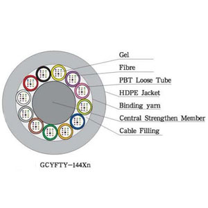
Micro-Cable for Fast Installation
Recleaving a fiber can be a substitute for cleaning, as it is hard to reliably clean fiber ends. For very high-quality fiber surfaces, or when using fibers with large diameter, or when attaching a fiber connector, it may be necessary to apply some polishing procedure after cleaving. One may, for example, insert the fiber end into a ferrule (a hollow ceramic, glass or metal tube) and fix it there with a glue.
The fiber is then polished down together with the glass tube, using a special polishing machine. This procedure allows one to produce a high-quality surface with an arbitrary well-defined orientation of the fiber surface. However, it takes substantially more time than simple cleaving, and of course it is essential to have all details of a polishing machine (e.g., the load force, speed and time) and the polishing agent well adapted to the ferrule and fiber material and size. Hand polishing is also possible, but usually leads to inferior results.
Polished fiber ends, other than cleaved ends, may have some convex curvature, resulting from the use of a flexible polishing pad. Such a “domed surface” facilitates a good contact e.g. between two single-mode fibers in a connector set.
Relevance of Cleave Angles
In some cases, it is important to have a cleaved fiber surface just perpendicular to the fiber axis. For example, this is often the case when a fiber is inserted into a fiber connector although some connectors require angle cleaves. Mechanical splices also don't work well with non-perpendicular ends (see Figure 1).

Figure 1: When a fiber cleave is not perpendicular, a fiber joint will not work well: an air gap will be formed, or alternatively a kink.
Note that due to refraction at the fiber end, a non-normal cleave causes a deviation of the output beam direction from the fiber axis (see Figure 2). Also, one then requires an appropriately tilted input beam for efficient launching. This makes the use of angle cleaves somewhat inconvenient.

Figure 2: When light comes out of a fiber with angled cleave, it will be somewhat deflected. The direction for reflected light is also shown; it will not go back to the fiber core.
The cleave angle also has an important influence on back-reflected light. If it is small, light reflected at the output surface (Fresnel reflection due to the index difference to air) will essentially travel backward in the fiber core. For large enough cleave angles, however, the light will entirely get into the cladding and will be lost there. This means that there is a very large return loss (e.g. 60dB) despite a significant reflection, which for a normal cleave would cause a return loss of only 14dB.
It depends on the fiber details how large the cleave angle needs to be for a high feedback suppression. For a usual single-mode fiber, for example, the mode has a beam divergence of several degrees. One may then require a cleave angle as large as 8°, for example. For a fiber with high numerical aperture, it may be even more. For large mode area fibers, however, rather small cleave angles are sufficient to suppress feedback.
In some cases, the Fresnel reflection from a fiber end is utilized, e.g. for an effective output coupler of a fiber laser, or in optical time domain reflectometry (OTDR).
For more fiber optics’ information, please browse our website or contact a Sopto representative by calling 86-755-36946668, or by sending an email to info@sopto.com.