-

- Sopto Home
-

- Special Topic
-

- Converter Knowledge
-

- How Gigabit Ethernet Works-Introduction
Converter Knowledge
- Form Factors and Application of Ethernet Media Converter
- Ethernet over 4 E1 Converter Brief Introduction
- What is the Difference between RS232 and RS485 Serial Interfaces
- What is the Difference between RS232 and RS485 Serial Interfaces
- How to Convert an Analog Telephone to VoIP Protocol?
- How to Find the Internet Protocol Address and Media Access Contr
- How to Convert from Fast Ethernet to Fiber Optics?
- How to Connect a Fiber Converter?
- How to Convert Ethernet to Fiber Media Converters?
SOPTO Special Topic
Certificate

Guarantee
Except products belongs to Bargain Shop section, all products are warranted by SOPTO only to purchasers for resale or for use in business or original equipment manufacturer, against defects in workmanship or materials under normal use (consumables, normal tear and wear excluded) for one year after date of purchase from SOPTO, unless otherwise stated...
Return Policies
Defective products will be accepted for exchange, at our discretion, within 14 days from receipt. Buyer might be requested to return the defective products to SOPTO for verification or authorized service location, as SOPTO designated, shipping costs prepaid. .....
Applications
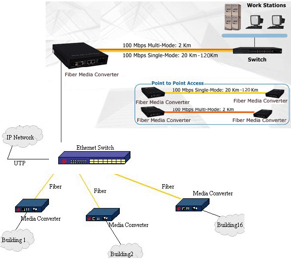
An Ethernet to Fiber Media Converter can also be used where there is high level of electromagnetic interference or EMI which is a common phenomenon found in industrial plants. This interference can cause corruption of data over copper-based ethernet links. Data transmitted over fiber optic cable however is completely immune to this type of noise. An Ethernet to Fiber Optic Converter therefore enables you to inter-connect your copper-ethernet devices over fiber ensuring optimal data transmission across the plant floor.
SOPTO Products
- Fiber Optic Transceiver Module
- High Speed Cable
- Fiber Optical Cable
- Fiber Optical Patch Cords
- Splitter CWDM DWDM
- PON Solution
- FTTH Box ODF Closure
- PCI-E Network Card
- Network Cables
- Fiber Optical Adapter
- Fiber Optical Attenuator
- Fiber Media Converter
- PDH Multiplexers
- Protocol Converter
- Digital Video Multiplexer
- Fiber Optical Tools
- Compatible
Related Products
Performance Feature
Converter Knowledge
Recommended
How Gigabit Ethernet Works-Introduction
Gigabit Ethernet allows network transfers up to 1.000 Mbps using standard Cat 5 UTP (unshielded twisted pair) cabling. How can this be accomplished, since Cat 5 cables can run only up to 100 Mbps? We will explain this and also other very interesting issues regarding Gigabit Ethernet performance.
Ethernet Cat 5 cables have eight wires (four pairs), but under 10BaseT and 100BaseT standards (10 Mbps and 100 Mbps, respectively) only four (two pairs) of these wires are actually used. One pair is used for transmitting data and the other pair is used for receiving data.
|
Pin |
Color |
Function |
|
1 |
White with Green |
+TD |
|
2 |
Green |
-TD |
|
3 |
White with Orange |
+RD |
|
4 |
Blue |
Not Used |
|
5 |
White with Blue |
Not Used |
|
6 |
Orange |
-RD |
|
7 |
White with Brown |
Not Used |
|
8 |
Brown |
Not Used |
Ethernet standard uses a technique against electromagnetic noise called cancellation. As electrical current is applied to a wire, it generates an electromagnetic field around the wire. If this field is strong enough, it can create electrical interference on the wires right next to it, corrupting the data that were being transmitted there. This problem is called crosstalk.
.png)
Figure 1 Cancellation technique
What cancellation does is to transmit the same signal twice, with the second signal “mirrored” (inverted polarity) compared to the first one, as you can see in Figure 1. So when receiving the two signals, the receiving device can compare the two signals, which must be equal but “mirrored”. The difference between the two signals is noise, making it very simple to the receiving device to know what is noise and to discard it. “+TD” wire standards for “Transmitting Data” and “+RD” wire standards for “Receiving Data”. “-TD” and “-RD” are the “mirrored” versions of the same signal being transmitted on “+TD” and “+RD” respectively.
Sopto supplies high quality fiber media converters, like Gigabit Media Converter, PSE Media Converter and so on. For the newest quotes, please contact a Sopto representative by calling 86-755-36946668, or by sending an email to info@sopto.com. For more info, please browse our website.

