-

- Sopto Home
-

- Special Topic
-
- Patch Cord Knowledge
-
- Patch Cable General Management

Patch Cord Knowledge
- Fiber Optic Connector Ferrule Design
- Fiber Optic Connector Design
- E2000 to ST Fiber Patch Cable Overview
- Acceptable and Unacceptable Fiber Connector End-Face Finishes
- Using Wipes and Cleaning Cassettes to Clean Fiber Patch Cords
- Not-Too-Tight Mating of Fiber Optic Connectors
- Matching Gel and Oils Contamination about Fiber Optic Connectors
- The Effect of Improper Use of Fiber Optic Connectors
- Why Fiber Optic Connectors are Fragile?
SOPTO Special Topic
Certificate


Guarantee
Except products belongs to Bargain Shop section, all products are warranted by SOPTO only to purchasers for resale or for use in business or original equipment manufacturer, against defects in workmanship or materials under normal use (consumables, normal tear and wear excluded) for one year after date of purchase from SOPTO, unless otherwise stated...
Return Policies
Defective products will be accepted for exchange, at our discretion, within 14 days from receipt. Buyer might be requested to return the defective products to SOPTO for verification or authorized service location, as SOPTO designated, shipping costs prepaid. .....
Applications
 Fiber Patch Cords have a widely application. Where the need for the optical fiber connection, where you need fiber optic patch cords.
Testing Equipment
FTTX+ LAN
Optical Fiber CATV
Optical Communication System
Telecommunication
SNS Page


SOPTO Products
- Fiber Optic Transceiver Module
- High Speed Cable
- Fiber Optical Cable
- Fiber Optical Patch Cords
- Splitter CWDM DWDM
- PON Solution
- FTTH Box ODF Closure
- PCI-E Network Card
- Network Cables
- Fiber Optical Adapter
- Fiber Optical Attenuator
- Fiber Media Converter
- PDH Multiplexers
- Protocol Converter
- Digital Video Multiplexer
- Fiber Optical Tools
- Compatible
Related Products
Performance Feature
Good Water-proof
Low insertion loss;
low reflection loss;
Stability, good repeatability;
High-precision ceramic ferrule;
Compatible with NTT standard;
Precision Grinding and fully testing;
Compliance with international standards
Patch Cord Knowledge
Recommended

Cable General Management
Labeling
Administration and Labeling for UTP and Fiber Optic Connecting Hardware and Cords should conform to TIA-606-B - Administration and Labeling Standard and Addenda. Cabling system administration, labeling and records are also covered in ISO/IEC 14763-1.
Labeling is the most important part of a System Administrator’s responsibilities. At any administration point in a cabling infrastructure, including patching panels, accurate labels are essential. These will identify pair modularity and tell technicians where the other end of the cable is terminated.
TIA-606-B requires that labels are visible and durable. They must be easily read by anyone carrying out work on the panel and have a design life at least as long as the patching hardware. Hand written labels are unacceptable; they must be printed by a mechanical device designed for the purpose.
Most patching panels have provision for inserting labels between the wiring blocks. These labels are color-coded to identify the origins of cables and include alphanumeric codes to provide additional information about the connections. On a port, for instance, they might identify the cabinet number, the shelf and the circuit board to which that particular set of patch cords is connected. TIA-606-B specifies the color-coding regime shown below
Termination type | Color | Pantone # | Typical Application |
demarcation point | orange | 150C | central office connection |
network connection | green | 353C | user side of central office connection |
common equipment | purple | 264C | connections to PBX, mainframe computer, LAN, multiplexer |
key system | red | 184C | connections to key telephone systems |
first level backbone | white |
| terminations of building backbone cable MC to ICs |
Second level backbones | gray | 422C | termination of building backbone cable connecting ICs to HCs |
campus backbone | brown | 465C | termination of backbone cable between buildings |
horizontal | blue | 291C | terminations of horizontal cable in TC’s |
miscellaneous | yellow | 101C | alarms, security, or energy management |
Some Information may be preprinted on labels supplied with the patch panel, but the Installer is usually responsible for supplying additional data.
Labeling Optical Fiber Cross Connects
Unlike labels for copper cross connects, optical fiber labels are not color-coded. However, fiber connectors may be color-coded to avoid joining fibers of different core size or type, which dramatically reduces throughput. Refer to ANSI/TIA-568-C.3 and/or ISO/IEC 11801 for requirements and recommendations for color-coding of multi-mode and single mode connectors. Instead of being inserted in a plastic strip, fiber labeling is often affixed to nearby surfaces such as a module door.
Information on the labels may include:
location of the far end of the fiber, e.g. the closest point to the optical connection in question, where the fiber either appears on a cross connect, appears on a wall or floor connector, or is connected to a piece of wall equipment
building room number
cable type
cable length
The figure below gives an example of the information contained on a fiber cross-connect label found in Room 3K-326 in Building 3
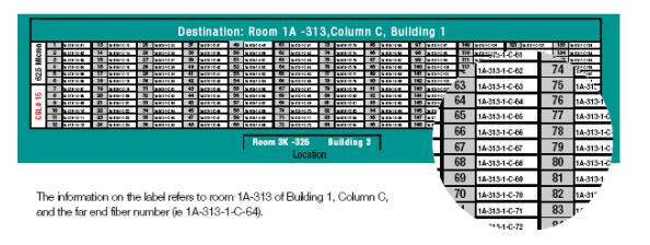
Note: If the TR/FD does not have a formal room number within the building, the room number should reflect the
informal TR/FD numbering system, which is described in the permanent records kept for each site. The fiber type is
62µm (i.e., 62.5/125 micron), cable 15 is the optical fiber cable between Room 3K-326 Building 3 and Room
1A-313, Building 1, and it is identified by the color code for red.
Change Requests
The starting point for all MACs is the Change Request. The process for raising and recording this request must be simple, efficient and rigidly enforced. Fundamental to this is designing a plain, simple change request form. This is the basic input document for the change management system and if it suffers from omissions or errors the whole change process may fail.
Whether the form is paper-based or electronic, time spent on designing it to capture all the necessary information and minimize risk errors is a good investment. Key information includes: names of staff making and authorizing requests, date, unique identifier number, services involved and of work required and location of connections. The form can also provide space for information about the user’s current service or this data can be obtained from your records.
Record Keeping
It is vital to keep records of all patching changes for reference during fault-finding and future moves, adds and changes. The records must include information on where cables go, what applications they support and how many pairs are available as spares. The labeling plan (see labeling section above) tells technicians the source of every cable by simply looking at the outlet or wiring block. In addition, the record system must allow users to track the equipment attached to those cables.
For horizontal links, TIA-606-B states that the following records may be kept:
a) Horizontal link identifier (primary indexing identifier, e.g. 1A-A47)
b) Cable type (e.g. 4-pair, UTP, Category 6, plenum)
c) Location of telecommunications outlet/connector (room, office, or grid location)
d) Outlet connector type (e.g. 8-position modular, T568-B wiring, Category 6)
e) Cable length (e.g. 51m/166ft)
f) Cross-connect hardware type (e.g. 48-port modular patch panel, T568-B wiring, Category 6)
Record systems can be set up using paper-based logbooks, spreadsheets or specialist software. The principles of completeness and clarity apply in all cases; it must always be easy to relate connectors and cords to the devices and services they support. The easier it is to search records of connections, the easier and quicker it is to manage patch cords. For larger systems, this gives a big advantage to software-based methods that allow machine searching of the records.
Intelligent Infrastructure Solutions
Network connections live or die in crowded data centers, wiring closets and telecom rooms, where a single misplaced patch cord can wreak havoc and increase downtime. Intelligent Infrastructure management solutions are designed to help manage patching and patch cords. They can help organizations respond to growing pressures to get MACs done more quickly with fewer resources.
The SOPTO Intelligent Infrastructure Solution integrates copper and fiber patching hardware with system control software to help monitor, document, and administer a complete communications infrastructure. Every port connection is continuously monitored, verified and logged in a central database, giving an immediate alert to any changes.
The system enables simple adherence to the best practices of planning, preparation, execution and validation of changes. Electronic work orders replace paper-based administration and improve productivity. Work is guided at each patch panel by electronic visual and audible prompts, helping to eliminate patching errors. Local and remote monitoring and information display further enhance productivity and ease of use.
Related Knowledge: