-

- Sopto Home
-

- Special Topic
-
- Module Knowledge
-
- Signal Transmission in the Bidirectional OSA Module

Module Knowledge
- Tips for Buying 10G XFP Transceivers
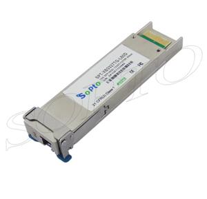
- XFP Transceivers for Telecommunications
- Three Types of Ethernet SFP Transceiver Modules Introduction
- Info about High Density CXP Optical Module
- Multipurpose CFP Optical Modules
- Info about CFP Management Interface
- SFP+ Transceivers Short Range Module Overview
- 3 Reasons Every Network Needs GLC-LH-SM Transceiver
- Is the GLC-SX-MM Transceiver Right for Your Switch?
SOPTO Special Topic
Certificate


Guarantee
Except products belongs to Bargain Shop section, all products are warranted by SOPTO only to purchasers for resale or for use in business or original equipment manufacturer, against defects in workmanship or materials under normal use (consumables, normal tear and wear excluded) for one year after date of purchase from SOPTO, unless otherwise stated...
Return Policies
Defective products will be accepted for exchange, at our discretion, within 14 days from receipt. Buyer might be requested to return the defective products to SOPTO for verification or authorized service location, as SOPTO designated, shipping costs prepaid. .....
Applications
 Fiber Optic Transceiver Modules can be applied to these occasions or fields.
Ethernet
IPTV
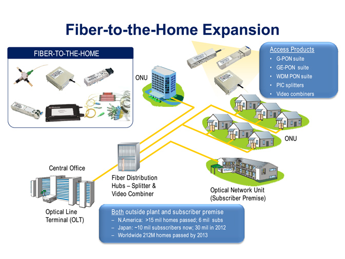
FTTX
Security
Video Monitor
SDH/SONET
Data Communication
Storage Area Networks
SNS Page


SOPTO Products
- Fiber Optic Transceiver Module
- High Speed Cable
- Fiber Optical Cable
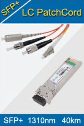
- Fiber Optical Patch Cords
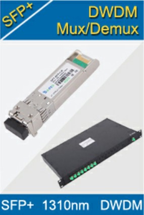
- Splitter CWDM DWDM
- PON Solution
- FTTH Box ODF Closure
- PCI-E Network Card
- Network Cables
- Fiber Optical Adapter
- Fiber Optical Attenuator
- Fiber Media Converter
- PDH Multiplexers
- Protocol Converter
- Digital Video Multiplexer
- Fiber Optical Tools
- Compatible
Related Products
 10G SFP+ Transceiver
 40G QSFP+ Transceiver
Performance Feature
Stable
Low cost
Small size
Economic
Dust-proof
High speed
Hot-pluggable
Good EMI, EMC
Wide appliaction field
DDM function available
Long transmission distance
Good Anti-static performance
Module Knowledge
Recommended
Signal Transmission in the Bidirectional OSA Module
As the mention in previous page, in this article, we will talk about the “signal transmission in the bidirectional OSA module”. The light transmission and receiving schemes of the OSA module are shown in Figure 1 (a).
.png)
Fig. 1 The bidirectional OSA module
(a) Light receiving and transmission schemes for the bidirectional optical link.
(b) A photograph of the assembled OSA module.
For light transmission (up-link), a wavelength of 850 nm (λ1) is used, and for light receiving (down-link), a wavelength of 1060 nm (λ2) is used. Two mirrors, mirror-1 and mirror-2, are located in the optical fiber array to transmit and receive the λ1 and λ2 optical signals, respectively.
In order to transmit the optical signal of wavelength, λ1, which is emitted from the VCSEL array, optical signals are sent through the hole and then reflected into the embedded fiber array by mirror-2. Because mirror-2 has wavelength-filtering layers, the incoming optical signal of wavelength λ2 passes mirror-2 and is then reflected at mirror-1 to the PD through the via hole of the PD-SiOB.
For the M-PD, the scattered light at the leakage window is also guided through the hole of the SiOB. A photograph of the OSA module is shown in Fig. 1(b), showing the three separate SiOBs for the PD, the VCSEL and the M-PD array chips.
For the leakage window under the M-PD, a scratch is formed only on the clad layer of the fiber to scatter the evanescent light wave. Evanescent waves for sensing and monitoring optical signals from the surfaces of optical waveguides are widely used in optical interconnection and optical sensor applications.
The working principle of our optical leakage window is based on that of a structure introduced earlier due to the effectiveness of its evanescent wave for monitoring with a small amount of loss of the transmitting light. In our structure, the leakage window was designed to scatter 5% (~0.2 dB) of the intensity of the transmitted light, which does not cause a significant loss in the optical link and which also provides enough light to the M-PD.
To scatter this amount of light, the depth of the scratch was estimated to be near 35 μm from the surface of the fiber by the measurement using a power meter. The scattered power was so sensitively varied near this depth that the detected powers showed considerable fluctuation from sample to sample. Thus, we controlled the scratching process to attain a detected power from each scratch within 2 dB of the transmitted power.
On the other hand, the evanescent field can be influenced by the variation of the modes in the fiber core, which could occur during the change of the intensity of the VCSEL source. However, the M-PD has a fairly low bandwidth compared to the modulation bandwidth of the light signal, and thus the time-averaged field should be less sensitive to the variation of the modes during high-speed modulation. In our experiment, the optical power detected from the M-PD was stably maintained during VCSEL modulation.
Notices: This article is reprinted from: opticsinfobase.org/oe/fulltext.cfm?uri=oe-22-2-1768&id=277085
For more, please see next page where we will intro the “Implementation of the OSA module and components Part 1”. By the way, Sopto supplies high quality fiber optical modules and fiber optical connectors with reasonable price. For the newest quotes, please contact a Sopto representative by calling 86-755-36946668, or by sending an email to info@sopto.com. For more info, please browse our website.
You May Like: