-

- Sopto Home
-

- Special Topic
-
- Module Knowledge
-
- Optical Transceiver Design for TDM PONs
Module Knowledge
- Tips for Buying 10G XFP Transceivers
- XFP Transceivers for Telecommunications
- Three Types of Ethernet SFP Transceiver Modules Introduction
- Info about High Density CXP Optical Module
- Multipurpose CFP Optical Modules
- Info about CFP Management Interface
- SFP+ Transceivers Short Range Module Overview
- 3 Reasons Every Network Needs GLC-LH-SM Transceiver
- Is the GLC-SX-MM Transceiver Right for Your Switch?
SOPTO Special Topic
Certificate


Guarantee
Except products belongs to Bargain Shop section, all products are warranted by SOPTO only to purchasers for resale or for use in business or original equipment manufacturer, against defects in workmanship or materials under normal use (consumables, normal tear and wear excluded) for one year after date of purchase from SOPTO, unless otherwise stated...
Return Policies
Defective products will be accepted for exchange, at our discretion, within 14 days from receipt. Buyer might be requested to return the defective products to SOPTO for verification or authorized service location, as SOPTO designated, shipping costs prepaid. .....
Applications
 Fiber Optic Transceiver Modules can be applied to these occasions or fields.
Ethernet
IPTV
FTTX
Security
Video Monitor
SDH/SONET
Data Communication
Storage Area Networks
SNS Page


SOPTO Products
- Fiber Optic Transceiver Module
- High Speed Cable
- Fiber Optical Cable
- Fiber Optical Patch Cords
- Splitter CWDM DWDM
- PON Solution
- FTTH Box ODF Closure
- PCI-E Network Card
- Network Cables
- Fiber Optical Adapter
- Fiber Optical Attenuator
- Fiber Media Converter
- PDH Multiplexers
- Protocol Converter
- Digital Video Multiplexer
- Fiber Optical Tools
- Compatible
Related Products
 10G SFP+ Transceiver
-180x180.JPG) 10G XENPAK
10G XENPAK 40G QSFP+ Transceiver
Performance Feature
Stable
Low cost
Small size
Economic
Dust-proof
High speed
Hot-pluggable
Good EMI, EMC
Wide appliaction field
DDM function available
Long transmission distance
Good Anti-static performance
Module Knowledge
Recommended
Optical Transceiver Design for TDM PONs
The optical transceiver (transmitter and receiver) used for optical-to-electrical conversion is a key component in optical communication systems. In a PON system, an optical transmitter and receiver at the optical line terminal (OLT) or optical network units (ONUs) are typically packaged together to form a bidirectional optical subassembly (BOSA).
The transmitter optical subassembly (TOSA) consists of a semiconductor laser (Fabry-Perot laser or DFB laser) and a laser driver. The receiver optical subassembly (ROSA) includes a photodiode (PIN or APD), a transimpedance amplifier, a limiting amplifier, and a clock and data recovery circuit. In addition to TOSA and ROSA, a duplex or tripex (WDM filter) is used to separate upstream and downstream wavelengths. The duplex or triplex is usually a thin-film filter, but optical filters (e.g., Bragg grating or a Mach-Zehnder interferometer) based on planar light-wave circuits are becoming a preferred option, as planar light-wave circuits are more compact, more reliable, and easier to assemble with TOSA and ROSA.
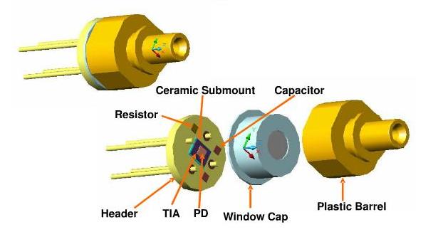
ROSA Basic Structure
As TDM PONs are being deployed on a large scale, significant effort has been put into designing an optical transceiver with improved performance, lower cost, and better reliability. The key challenges in developing optical transceivers for FTTx applications are a higher level of integration, cost-effective packaging, and burst-mode optical transmission technologies in the upstream link. For integration and packaging, optical transceivers are evolving toward planar light-wave circuits and monolithic photonic integrated circuits.
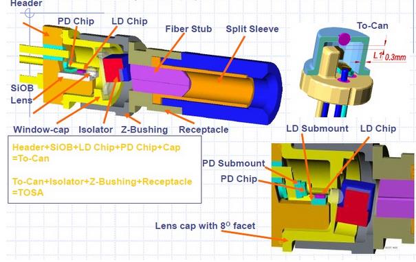
TOSA Basic Structure
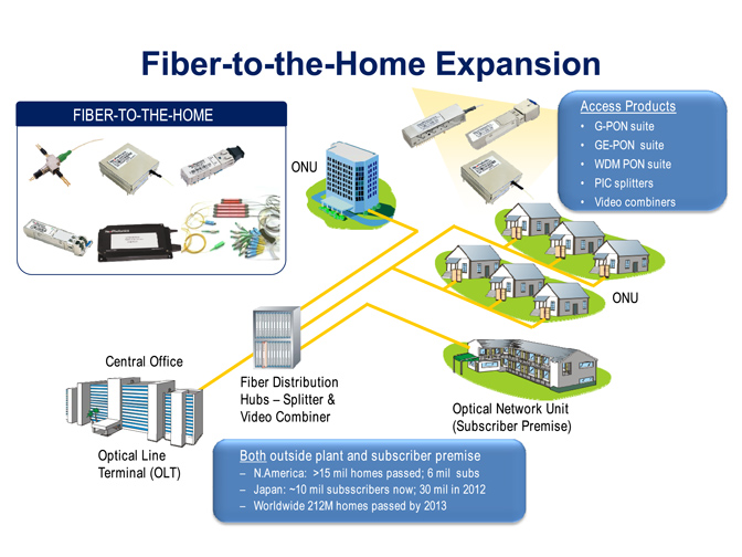
In a TDM PON system, all the users share the same fiber infrastructure from an OLT to the distribution node. In the downstream direction, data packets are broadcast to all ONUs. OLT transmitters and ONU receivers operate in a continuous mode, where synchronization is maintained at all times. Even if there are no data to send to ONUs, the OLT transmitter has to transmit idle bit patterns so that the ONUs’ receiver can retrieve the clock continuously from the downstream signal.
However, in the upstream direction, all the users have to be avoided in the upstream transmission, so at any given time, only one packet (from one ONU) is allowed to reach the central office. The OLT coordinates the upstream transmission and schedules the transmission time for each ONU. When an ONU wants to send data to the OLT, it transmits a burst of data in the time assigned by the OLT and then turns off its transmitter completely to avoid interfering with other ONUs’ upstream transmission. Bursts of data from different ONUs following each other to the receiver at the central office are separated by a certain guard time. This type of transmission is called burst-mode transmission.
Here is a figure that compares the data formats of continuous- and burst-mode transmission. Burst-mode transmitter at each ONU and a burst-mode receiver at the central office are indispensable. A burst-mode receiver at rhe central office is required to have various affordable input ranges and fast clock locking times. On the other hand, a burst-mode transmitter, located on the user side, has to show fast turn-on time as well as good power suppression during an idle state. Designing high-speed burst-mode optical transceivers is necessary and challenging when deploying passive optical networks.
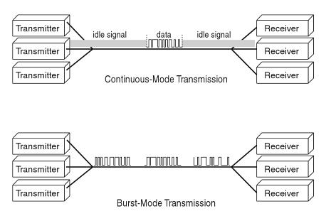
Continuous-Mode and Burst-Mode Transmission
Burst-Mode Laser Drivers
A burst-mode transmitter has to show fast turn-on time as well as good power suppression. The design challenges for burst-mode laser/modulator drivers are rise and fall times and automatic power control. Conventional driver circuits are designed to maintain a constant bias current and voltage. However, good optical power suppression in the idle state requires that the bias be turned off quickly. Driver circuits have to be designed to have short turn-on/off performance. For automatic power control, conventional circuits often use slow monitor photodiode and/or analog filters to average the signal and an analog control loop to analog control loops. It is necessary to monitor optical output sampled at appropriate points in burst waveform.
Burst-Mode Receivers
Conventional optical receivers cannot be used for burst-mode detection because they are not able instantaneously to handle various packets arriving with large differences in optical power and phase alignment. It is therefore necessary to design receivers that can adapt to the variation in optical power and phase alignment on a packet-by-packet basis. The design challenges for burst-mode receivers are dynamic sensitivity recovery, level recovery, and fast clock recovery.
When a weak burst follows a strong burst, it is difficult to detect the weak signal. Dynamic sensitivity recovery is necessary for detection of the weak signal. The recovery of the weak burst is limited by photodiode carrier transport effects, amplifier slew and charging rates, and unintentional automatic gain control effects.
For level recovery, a burst-mode receiver can be designed with a feedback or feed forward structure. For the feedback design, a differential input/output transimpedance amplifier and peak detection circuit form a feedback loop, whereas in the feed forward design, the signal from the preamplifier is feed forward into a peak detection circuitry. Both designs have been implemented in practice. A feedback structure enables the receiver to work more reliably, but a different input/output preamplifier is needed. A feed forward receiver has a faster response time and a conventional decoupled preamplifier can be used, but the circuitry needs to be designed carefully to prevent oscillation in the receiver. Level recovery circuits with simple and robust design and good performance are still an open issue that requires further investigation.
We provide optical transceivers not only for TDM PONs; we also offer compatible transceiver modules worldwide. Welcome to visit our website where you can find the modules you want to buy. Our optical modules can be compatible with all brands, such as the SFP modules.
For purchasing more high quality fiber optic transceivers with low cost or for more products’ information, please contact a Sopto representative by calling 86-755-36946668, or by sending an email to info@sopto.com.
You May Like: