-

- Sopto Home
-

- Special Topic
-
- Module Knowledge
-
- Implementation of the OSA Module and Components Part 2
Module Knowledge
- Tips for Buying 10G XFP Transceivers
- XFP Transceivers for Telecommunications
- Three Types of Ethernet SFP Transceiver Modules Introduction
- Info about High Density CXP Optical Module
- Multipurpose CFP Optical Modules
- Info about CFP Management Interface
- SFP+ Transceivers Short Range Module Overview
- 3 Reasons Every Network Needs GLC-LH-SM Transceiver
- Is the GLC-SX-MM Transceiver Right for Your Switch?
SOPTO Special Topic
Certificate


Guarantee
Except products belongs to Bargain Shop section, all products are warranted by SOPTO only to purchasers for resale or for use in business or original equipment manufacturer, against defects in workmanship or materials under normal use (consumables, normal tear and wear excluded) for one year after date of purchase from SOPTO, unless otherwise stated...
Return Policies
Defective products will be accepted for exchange, at our discretion, within 14 days from receipt. Buyer might be requested to return the defective products to SOPTO for verification or authorized service location, as SOPTO designated, shipping costs prepaid. .....
Applications
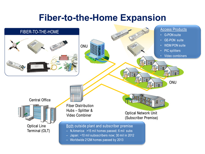 Fiber Optic Transceiver Modules can be applied to these occasions or fields.
Ethernet
IPTV
FTTX
Security
Video Monitor
SDH/SONET
Data Communication
Storage Area Networks
SNS Page


SOPTO Products
- Fiber Optic Transceiver Module
- High Speed Cable
- Fiber Optical Cable
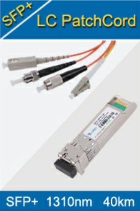
- Fiber Optical Patch Cords
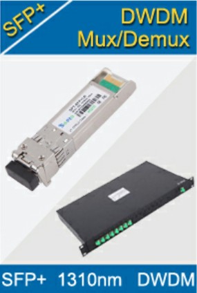
- Splitter CWDM DWDM
- PON Solution
- FTTH Box ODF Closure
- PCI-E Network Card
- Network Cables
- Fiber Optical Adapter
- Fiber Optical Attenuator
- Fiber Media Converter
- PDH Multiplexers
- Protocol Converter
- Digital Video Multiplexer
- Fiber Optical Tools
- Compatible
Related Products
 10G SFP+ Transceiver
 40G QSFP+ Transceiver
Performance Feature
Stable
Low cost
Small size
Economic
Dust-proof
High speed
Hot-pluggable
Good EMI, EMC
Wide appliaction field
DDM function available
Long transmission distance
Good Anti-static performance
Module Knowledge
Recommended
Implementation of the OSA Module and Components Part 2
Reliability tests of optical components
The results of the reliability test for the VCSEL and PD are shown in Fig. 1
.png)
Figure 1 Results of the reliability test during the thermal variation assessment
The VCSEL light power and PD responsivities are compared before and after thermal variation: (a) light power at 850 nm, (b) light power at 1060 nm, (c) responsivity at 850 nm, and (d) responsivity at 1060 nm.
The reliability tests of the VCSEL light power and the responsivity of the PD for the two wavelengths of 850 nm and 1060 nm were assessed during thermal variation of 50 cycles in a range of 0 þC ~70 þC, following the Telcordia reliability assurance requirements (GR-468). After the thermal variation, the change of the VCSEL threshold current, Ith, was less than 0.8 mA.
4.25G 850nm 300m SFP Optical Transceiver with 850nm VCSEL laser transmitter
Before the thermal variation, the average output light power of the VCSEL arrays were 2 mW and 0.7 mW at wavelengths of 850 nm and 1060 nm, respectively, and the average responsivities of PD arrays were 0.35 A/W and 0.65 A/W at wavelengths of 850 nm and 1060 nm, respectively. After thermal variation, the change in these VCSEL output light power and PD responsivities are less than 10% changes, as shown in Figs. 1 (a)-(d).
However, these results indicate that the change of the VCSEL output light power is slightly more severe than the change of the PD responsivity due to the inherent thermal sensitivity of the VCSEL light power.
Optical link loss measurement
In order to analyze the end-to-end optical signal transmission, the coupling losses from the VCSEL to the PD light path were measured using the measurement setup shown in Fig. 2
.png)
Figure 2 Light transmission scheme of an end-to-end optical link using the proposed bidirectional OSA modules
The coupling loss measurement is done both with and without M-PD to ascertain that the optical losses are within the available power budget. The measured coupling losses with and without M-PD shown in Table 1 are taken as the average of all four-channels. The optical coupling loss from the VCSEL to the fiber at a wavelength of 1060 nm is higher than the coupling loss at 850 nm.
This result may be due to the higher full-width divergence angle of 33þ in the 1060 nm VCSEL compared to that divergence angle of 19þ in the 850 nm VCSEL. The aperture sizes of the PDs are 60 µm and 50 µm for wavelengths of 850 nm and 1060 nm, respectively, having only a small difference. Thus, it could explain the result of that the coupling losses from the fiber to PD show relatively small differences at 850 nm and 1060 nm.
Table 1 End-to-end Optical Coupling Loss of the OSA-based Bidirectional Optical Link
|
Coupled Device and Wavelength |
Optical Coupling Loss (dB) |
Total Coupling Loss (dB) |
||
|
VCSEL -> Fiber |
Fiber-> PD |
|||
|
VCSEL without M-PD |
@850nm |
0.6 |
0.8 |
1.4 |
|
@1060nn |
2.4 |
0.7 |
3.1 |
|
|
VCSEL with M-PD |
@850nm |
1.4 |
2.7 |
4.1 |
|
@1060nn |
3 |
1.8 |
4.8 |
|
The measurement results of the total coupling loss for end-to-end coupling in the bidirectional optical link with and without M-PDs are shown in Fig.3 (a) and (b), respectively. The total coupling loss with M-PD including the coupling losses from the VCSEL to the fiber and from the fiber to the PD is slightly higher than that in the case without the M-PD component. This may be due to the loss of the optical signal caused by the leakage windows which are formed in the samples coupled with the M-PD, as revealed in Table 1.
The increment of the loss (in the average value of the four channels) attributed to the leakage window for each coupling is dispersed in the range of 0.6 ~1.9, which is higher than our target value (0.2 dB) established in the design of the leakage window. Thus, to reduce this loss, careful control of V-scratch may be required in the sawing process to form the leakage window. Nevertheless, the total coupling losses from the VCSEL to the PD are less than 5 dB for both the 850 nm and 1060 nm optical links with and without the M-PD component, which indicates that the available power budget of the optical link should be higher than this value.
.png)
Fig. 3 The measured coupling loss of the bidirectional end-to-end optical link: (a) without M-PD and (b) with M-PD components.
Power budget of the optical link
The measurements of the coupling losses discussed in the previous section are used to estimate the available power budget and power margin for the transmission of optical signals within 100 m.
Table 2 Specifications for the End-to-end Optical Link Power Budget Estimation
|
Category |
Item |
@850nm |
@1060nm |
|
|
Measured |
Tx power (PTx), dBm |
2 |
-1.5 |
|
|
Measured |
Coupling loss (PCL), dB |
4.1 |
4.8 |
|
|
Measured |
Rx sensitivity (PRx), dBm |
-12.4 |
-15.1 |
|
|
Recommended |
Margin (Pm), dB |
2 |
2 |
|
|
Recommended |
Distance (L), m |
<100 |
<100 |
|
|
Standard |
Fiber loss (PF), dB/km |
2.2 |
1.1 |
|
Table 2 shows a summary of the specifications (measured and recommended values) for the estimation of the end-to-end optical link power budget and power margin at a data rate of 10 Gb/s using a multi-mode fiber (MMF) array with a core size of 50 µm. The sensitivity of the Rx module is estimated using an Rx input sensitivity of 20 µA and the minimum PD responsivity from the measured results shown in Figs. 1(b) and (d). The measured minimum PD responsivity is 0.35 A/W and 0.65 A/W at wavelengths of 850 nm and 1060 nm, respectively.
The estimated input sensitivity levels of the Rx modules are −12.4 dBm and −15.1 dBm at wavelengths of 850 nm and 1060 nm, respectively. Similarly, the available output power of the Tx modules is estimated from the measured results of the VCSEL light power shown in Figs. 1(a) and (c). The available VCSEL light power levels are equal to 2 dBm and −1.5 dBm at wavelengths of 850 nm and 1060 nm, respectively.
Using the data (recommended and/or measured) shown in Table 2, we can estimate the available power budget of the end-to-end optical link. This is obtained by subtracting the minimum receiver input power, PRx, from the transmitter power, PTx. The optical power losses in the link between two OSA modules are the summation of the total coupling loss PCL and the optical loss in the fiber PFL. In order to transmit data reliably through an optical link, the available power budget should be greater than the optical link power losses as
PTx−PRx>PCL+PFL
From Eq. (1), we can also determine the maximum available power margin, PMM, for the bidirectional optical link, as
PMM=(PTx−PRx)−(PCL+PFL).
The maximum available power margin, PMM, can be further reduced by considering other impairments, such as inter-channel, inter-mode and inter-symbol types of interference. These forms of interference can also affect the bandwidth of the signal transmission and the transmission distance.
Thus, the available power budget of the optical link can be simply estimated from Eq. (1), which involves the subtraction of the Rx sensitivity power, PRx, from the Tx power, PTx. These values are approximately 14.4 dB and 13.6 dB for wavelengths of 850 nm and 1060 nm, respectively. In contrast, the optical link power losses are also obtained using Eq. (1) by adding the PCL and PFL losses, estimated as 6.3 dB and 6.9 dB at wavelengths of 850 nm and 1060 nm, respectively. Using Eq. (2), the estimated maximum available power margins are 8.1 dB and 6.7 dB at wavelengths of 850 nm and 1060 nm, respectively.
These maximally available power margins are greater than the required power margin of 2 dB, which is required for most optical interconnect systems. Hence, the bidirectional optical link with the proposed OSA modules can be utilized for transmitting data signals within 100 m. However, the achievable distance could be reduced due to various forms of signal impairment.
Notices: This article is reprinted from: opticsinfobase.org/oe/fulltext.cfm?uri=oe-22-2-1768&id=277085
For more, please see next page where we will intro the “Experimental Results”. By the way, Sopto supplies high quality fiber optical modules and fiber optical connectors with reasonable price. For the newest quotes, please contact a Sopto representative by calling 86-755-36946668, or by sending an email to info@sopto.com. For more info, please browse our website.
You May Like: