-

- Sopto Home
-

- Special Topic
-
- Module Knowledge
-
- Implementation of the OSA Module and Components Part 1

Module Knowledge
- Tips for Buying 10G XFP Transceivers
- XFP Transceivers for Telecommunications
- Three Types of Ethernet SFP Transceiver Modules Introduction
- Info about High Density CXP Optical Module
- Multipurpose CFP Optical Modules
- Info about CFP Management Interface
- SFP+ Transceivers Short Range Module Overview
- 3 Reasons Every Network Needs GLC-LH-SM Transceiver
- Is the GLC-SX-MM Transceiver Right for Your Switch?
SOPTO Special Topic
Certificate


Guarantee
Except products belongs to Bargain Shop section, all products are warranted by SOPTO only to purchasers for resale or for use in business or original equipment manufacturer, against defects in workmanship or materials under normal use (consumables, normal tear and wear excluded) for one year after date of purchase from SOPTO, unless otherwise stated...
Return Policies
Defective products will be accepted for exchange, at our discretion, within 14 days from receipt. Buyer might be requested to return the defective products to SOPTO for verification or authorized service location, as SOPTO designated, shipping costs prepaid. .....
Applications
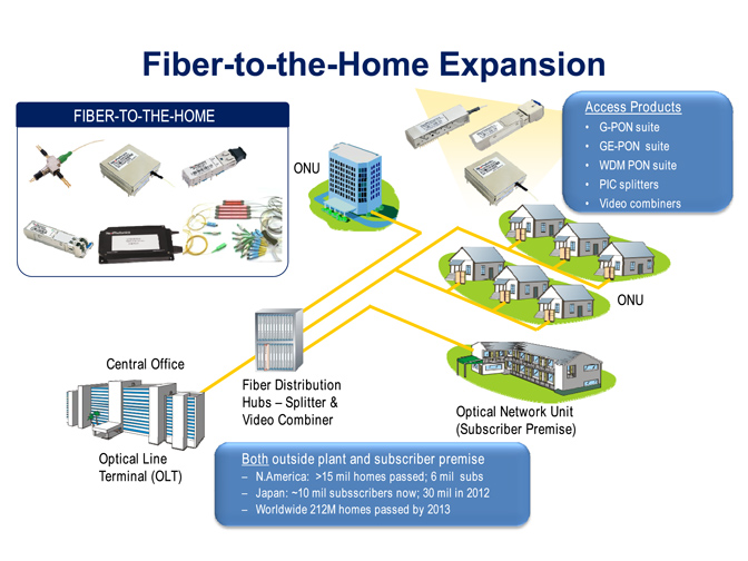 Fiber Optic Transceiver Modules can be applied to these occasions or fields.
Ethernet
IPTV
FTTX
Security
Video Monitor
SDH/SONET
Data Communication
Storage Area Networks
SNS Page


SOPTO Products
- Fiber Optic Transceiver Module
- High Speed Cable
- Fiber Optical Cable
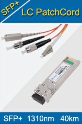
- Fiber Optical Patch Cords
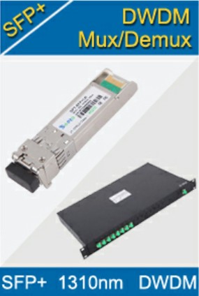
- Splitter CWDM DWDM
- PON Solution
- FTTH Box ODF Closure
- PCI-E Network Card
- Network Cables
- Fiber Optical Adapter
- Fiber Optical Attenuator
- Fiber Media Converter
- PDH Multiplexers
- Protocol Converter
- Digital Video Multiplexer
- Fiber Optical Tools
- Compatible
Related Products
 10G SFP+ Transceiver
 40G QSFP+ Transceiver
Performance Feature
Stable
Low cost
Small size
Economic
Dust-proof
High speed
Hot-pluggable
Good EMI, EMC
Wide appliaction field
DDM function available
Long transmission distance
Good Anti-static performance
Module Knowledge
Recommended
Implementation of the OSA Module and Components Part 1
The stability, the coupling loss and the crosstalk noise of the four-channel OSA module were measured for error-free and successful data transmission in the bidirectional optical link. Thermal shock tests were also done to evaluate the reliability of the device and to assess the parasitic heating effects with temperature changes.
The optical crosstalk between the channels of the OSA module was measured to verify the presence of inter-channel isolation. Further, the coupling losses from the VCSEL to the fiber and from the fiber to the PD were measured to estimate the available power budget and power margin for the transmission of optical signals up to 100 m.
Wavelength separation of the bidirectional link and crosstalk
In the design of our TRx module, two wavelengths of 850 nm and 1060 nm are utilized to reduce the optical crosstalk between the up- and down-link for error-free data transmission. Meanwhile, VCSELs for optical interconnect applications which work with wavelengths of 850 nm and 980 nm are well developed and effectively being utilized in optical interconnect applications, operating at high data rates. Hence, utilizing these two wavelengths of 850 nm and 980 nm can help to isolate the signals between the up- and down-link. However, the responsivities of the PDs to detect these wavelengths could overlap, as shown in Fig. 1
.png)
Fig. 1 The relative responsivities of PDs for different wavelengths
Figure 1 shows the responsivities of commercially available PDs for In0.5Ga0.5P/GaAs and In0.5Ga0.5As/GaAs PIN PDs, as used in this work to detect the 850 nm and 1060 wavelengths, respectively. The responsivity of an In0.53Ga0.47As/In0.52Al0.48As PIN PD for 980 nm is also compared. Each responsivity curve is normalized to its own maximum.
As shown in Fig. 1, the responsivity of PIN PDs is usually wider than the wavelength of interest, which may also vary with the temperature. This can lead to crosstalk and signal reliability issues. Thus, in the proposed bidirectional OSA module design, we choose the two wavelengths of 850 nm and 1060 nm, as these wavelengths show less overlap in the responsivity curves of the corresponding PDs. Hence, using two wavelengths with wider separation reduces the optical crosstalk between the transmitted and the received optical signals.
.png)
Figure 2 Light transmission scheme of an end-to-end optical link using the proposed bidirectional OSA modules
In order to accomplish bidirectional transmission using wavelengths of 850 nm and 1060 nm, two kinds of wavelength-filtering mirrors are required. For the up-link module sending signals from an 850 nm VCSEL, the wavelength-filtering mirror (mirror-2) requires reflection of the 850nm wavelength and transmission of the 1060 nm wavelength. For the down-link module sending signals from a 1060 nm VCSEL, the mirror requires reflection of the 1060nm wavelength and transmission of the 850 nm wavelength.
155M SFP BIDl Transceiver 80km 1490/1550nm
A detailed description of this wavelength management scheme for data transmission will be given later in Fig. 2. The wavelength-filtering mirrors were prepared by the deposition of 20 periods of Ti3O5/SiO2 layers on the 45°-polished silica fiber. For filtering the 850 nm wavelength, Ti3O5 layer was deposited first, and for filtering the 1060 nm wavelength, SiO2 layer was deposited first on the silica surface.
.png)
Fig. 3 Simulated transmittance vs wavelength curves for the wavelength-filtering mirrors used in the OSA modules (a) for the up-link and (b) for the down-link.
Figure 3 shows the simulation data of the transmittances for the two kinds of wavelength-filtering mirrors. The simulation result shows the reversed transmittances for the 850 nm and 1060 wavelengths for the two mirrors. The transmittance and reflectance were also identified experimentally in the four-channel modules, as presented in Fig. 4
.png)
Fig. 4 Measured transmittances and reflectances of the wavelength-filtering mirrors (a) for the up-link and (b) for the down-link
The measured transmittance of light is about 85 ~88% for the 850 nm wavelength and the reflectance is about ~95% for the 1060 nm wavelength in the up-link module, as shown in Fig. 4(a). While, in the down-link module the transmittance is about 86 ~89% for 1060 nm and the reflectance is about ~95% for 850 nm, as seen in Fig. 4(b).
Note here that for mirror-1 at the end of the fiber, we also deposited wavelength-filtering layers, reversing the filtering wavelengths relative to the layers for mirror-2. Specifically, 850 nm filtering layers are deposited on mirror-1 for the up-link module and 1060 nm filtering layers for the down-link module. Those depositions exhaustively remove the optical crosstalk on the receiver sides. Hence, the crosstalk between the up- and down-link can be minimized.
Note also that if the fiber segments are prepared by coating the 850 nm and 1060 nm filtering layers on each 45° end of the segments, they can be used for both the up- and down-link modules, just selecting one end corresponding to mirror-2 and attaching to the main transmission fiber. Thus, the coating on mirror-1 does not incur an additional cost in the processes of preparing the two kinds of mirrors.
.png)
Fig. 5 The measured optical crosstalk of the bidirectional optical link (a) without the M-PD and (b) with the M-PD components
Figure 5 shows the measured optical crosstalk of each channel with and without the M-PD component. The typical optical crosstalk between the channels is about −45 dB. A higher crosstalk value is obtained for the OSA module with M-PD. This can be attributed to the higher loss due to the presence of the M-PD at the leakage window.
Notices: This article is reprinted from: opticsinfobase.org/oe/fulltext.cfm?uri=oe-22-2-1768&id=277085
For more, please see next page where we will intro the “Implementation of the OSA module and components Part 2”. By the way, Sopto supplies high quality fiber optical modules and fiber optical connectors with reasonable price. For the newest quotes, please contact a Sopto representative by calling 86-755-36946668, or by sending an email to info@sopto.com. For more info, please browse our website.
You May Like: