-

- Sopto Home
-

- Special Topic
-
- Module Knowledge
-
- Optical Module-Analog Laser Drive Circuits
Module Knowledge
- Tips for Buying 10G XFP Transceivers
- XFP Transceivers for Telecommunications
- Three Types of Ethernet SFP Transceiver Modules Introduction
- Info about High Density CXP Optical Module
- Multipurpose CFP Optical Modules
- Info about CFP Management Interface
- SFP+ Transceivers Short Range Module Overview
- 3 Reasons Every Network Needs GLC-LH-SM Transceiver
- Is the GLC-SX-MM Transceiver Right for Your Switch?
SOPTO Special Topic
Certificate


Guarantee
Except products belongs to Bargain Shop section, all products are warranted by SOPTO only to purchasers for resale or for use in business or original equipment manufacturer, against defects in workmanship or materials under normal use (consumables, normal tear and wear excluded) for one year after date of purchase from SOPTO, unless otherwise stated...
Return Policies
Defective products will be accepted for exchange, at our discretion, within 14 days from receipt. Buyer might be requested to return the defective products to SOPTO for verification or authorized service location, as SOPTO designated, shipping costs prepaid. .....
Applications
 Fiber Optic Transceiver Modules can be applied to these occasions or fields.
Ethernet
IPTV
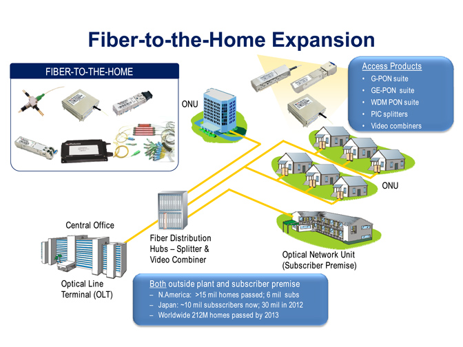
FTTX
Security
Video Monitor
SDH/SONET
Data Communication
Storage Area Networks
SNS Page


SOPTO Products
- Fiber Optic Transceiver Module
- High Speed Cable
- Fiber Optical Cable
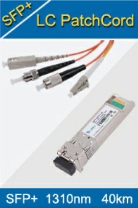
- Fiber Optical Patch Cords
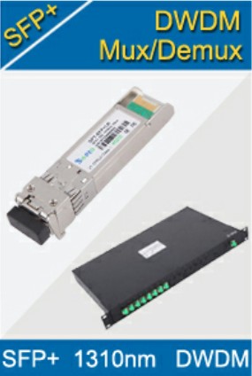
- Splitter CWDM DWDM
- PON Solution
- FTTH Box ODF Closure
- PCI-E Network Card
- Network Cables
- Fiber Optical Adapter
- Fiber Optical Attenuator
- Fiber Media Converter
- PDH Multiplexers
- Protocol Converter
- Digital Video Multiplexer
- Fiber Optical Tools
- Compatible
Related Products
 10G SFP+ Transceiver
 40G QSFP+ Transceiver
Performance Feature
Stable
Low cost
Small size
Economic
Dust-proof
High speed
Hot-pluggable
Good EMI, EMC
Wide appliaction field
DDM function available
Long transmission distance
Good Anti-static performance
Module Knowledge
Recommended
Analog Laser Drive Circuits
Figure 7 illustrates two common circuit configurations used to drive lasers for analog applications. The simpler of the two, shown in figure 7a, offers moderate linearity and good performance in frequencies up to 500 MHz. The analog signal path only involves C1, R1, Q1, R2, and D1, the laser diode. Q1 acts as a transconductant stage in which voltage flows in and current flows out. C1 passes only the AC portion of the analog input signal.
R1, usually only a few tens of Ohms, squelches any possible oscillations in Q1. The AC portion of analog input voltage VIN appears at the base of Q1 and also at the emitter of Q1. VIN, the AC voltage at the emitter of Q1, imposes across R2 to create a modulation current VIN/R2. U1 supplies DC current to the laser through R3 and R1. U1 creates a servo loop that maintains a constant photodiode current through the rear facet monitor PIN diode.
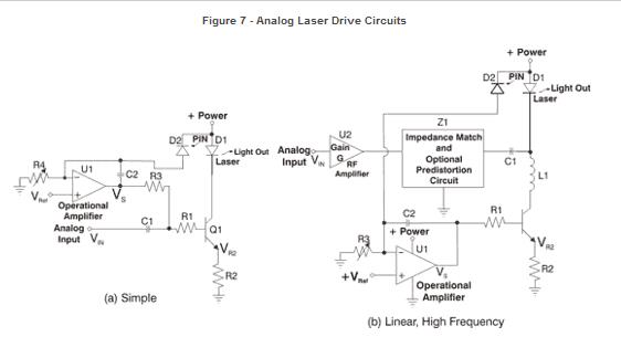
The circuit illustrated in Figure 7a indirectly maintains constant laser optical output. The rear facet monitor PIN diode receives light from one end of the laser chip while the other end of the chip illuminates the optical fiber. While the light in the fiber correlates to light in the monitor PIN diode, it never matches exactly at all output and environmental conditions, an phenomenon called tracking error. Figure 7b shows a more advanced analog laser circuit, offering good to excellent linearity at very high frequencies (GHz).
The signal path of this circuit only involves U2, Z1, C1, and the laser diode, D1. Amplifier U2 provides input matching, gain and isolates the laser from outside conditions. The block labeled Z1 can take on many functions. At a minimum, it interfaces the output of the amplifier U2, usually 50 or 75Ohms, to the laser that has an impedance ranging from 5 Ohms to 25 Ohms. As shown, sometimes the laser package incorporates this impedance matching. Digital Laser Drive Circuits
Figure 8 illustrates two common discrete component circuit configurations that function to drive lasers for digital applications. However, a wide variety of highly integrated ICs exist because of the high demand for digital laser drivers. The discrete component circuit configurations illustrate the most commonly used principles in commercially available laser driver ICs.
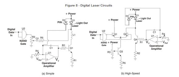
Figure 8a illustrates a simple circuit that is utilized at frequencies to several hundred megahertz. "Digital data in" takes a relatively simple path. The NAND gate, U2, buffers the signal and provides fast and consistent edges. Potentiometer, R3, adjusts the amplitude of the laser's oncoming digital signal, usually referred to as a modulation depth adjustment.
Capacitor, C2, block any DC component, allowing the AC component of the "digital data in" to pass. Incidentally, nearly all digital laser drive circuits cannot handle a DC component in the "digital data in" signal, meaning that the "digital data in" signal must always have transitions present.
Resistor, R5, provides impedance matching into the laser, and feeds directly into the cathode of the laser, D1. Inductor, L1, allows the AC component of the "digital data in" signal to reach the laser, as well as a DC signal. The rear facet monitor photodiode, D2, outputs a current proportional to the laser output. The current out of D2 goes to a servo loop, ensuring that the average optical output of D1 remains constant. U1 forms the heart of the servo loop. Capacitor, C1, configures U1 as an integrator. The +input of U1 remains at a positive voltage, VREF.
The value of VREF usually lies midway between ground and +Power. Potentiometer, R4, adjusts the average optical output power of the laser D1 by sinking a current out of the -input of U1. This negative current causes the output of U1, referred to as V2, to increase. As V2 increases, transistor Q1 turns on. This causes an increasing current to flow through both L1 and D1. As the current through D1 increases, the average optical output of D1 increases, which causes the current from D2, the rear facet monitor photodiode, to increase. This continues until the current out of D2 matches the current being sinked by potentiometer, R4.
R4, usually referred to as the "power adjust" in digital laser drive circuits, sets the rear facet monitor photodiode current. The average optical output power and the rear facet monitor photodiode current are nearly equal, differing only by tracking error. Three components in the circuit, C2, L1, and C1, function to limit the low-frequency, and thus limiting low data rate operations. Normally, a digital laser driver circuit should handle frequencies as low as 1/100th of the design data rate.
Therefore, a laser driver designed to handle a 622 Mb/s data rate must also handle frequencies as low as 6.22 MHz. The more complex circuit shown in Figure 8b allows very high, multi-gigabit speeds. With only the omission of L1, the servo loop portion of the circuit matches the circuit in Figure 8a. L1 is replaced in this circuit by Q4 a very fast , low capacitance transistor. To not interfere with the modulation signal, Q4's collector will appear as a current source. Potentiometer, R4, sets the rear facet monitor photodiode current or average optical output power.
The "digital data in" signal first goes through the NAND gate, U2, as in the first circuit. However, this circuit incorporates a NAND gate with the differential outputs of U2 to drive a transistor-based differential amplifier consisting of Q1 and Q2. Transistor Q3 forms a constant current source. The potentiometer, R3, sets the current flowing in the collector of Q3.
The current flowing out of Q3 determines the amount of modulation current that is switched to the laser in response to 1's and 0's. The modulation current from the collector of Q3 oscillates between the +power line (by Q1) and the laser, D1, (by Q2), as the outputs of U2 switch back and forth. To avoid a circuit becoming slow, the digital laser circuit must avoid saturation. Q1, Q2 and Q3 all operate in a linear mode in circuit 8b allowing them to operate at very high speeds.
Related Knowledge:
- Optical Module-Analog Laser Drive Circuits
- Optical Module-Backreflection
- Optical Module-Laser Types
- Optical Module-CWDM and DWDM
- Fiber optic transceiver and fiber connectors
Guess Products You May Like: