-

- Sopto Home
-

- Special Topic
-

- Fiber Optics knowledge
-

- How to Manage Fiber Optic Attenuation?
Fiber Optics knowledge
- Maintained Methods of Fusion Splicer Parts
- How to Use the Fiber Optic Cleaver?
- What are Fixed Attenuators & Variable Attenuators?
- Deployable Fiber Optic Systems for Harsh Mining Environments
- Developing Miniature Fiber Optic Cable Has Become the Trend
- Fiber Optic Cleaning Procedures
- 6 Steps to Selecting a Fiber Optic Cable
- Signal Attenuation Introduction
- How Fiber Transmission Works?
SOPTO Special Topic
Certificate
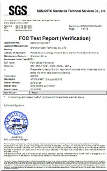

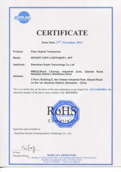
Guarantee
Except products belongs to Bargain Shop section, all products are warranted by SOPTO only to purchasers for resale or for use in business or original equipment manufacturer, against defects in workmanship or materials under normal use (consumables, normal tear and wear excluded) for one year after date of purchase from SOPTO, unless otherwise stated...
Return Policies
Defective products will be accepted for exchange, at our discretion, within 14 days from receipt. Buyer might be requested to return the defective products to SOPTO for verification or authorized service location, as SOPTO designated, shipping costs prepaid. .....
Applications
Fiber Optis can be used in so many fields:
Data Storage Equipment
Interconnects,Networking
Gigabit Ethernet
FTTx, HDTV,CATV
Aerospace & Avionics
Data Transfer Tests
Network Equipment
Broadcast Automotive
Electronics,Sensing
Oil & Gas, Imaging
Outside Plant,Central Office
Harsh Environment
Data Transmission
Illumination,Institutions
Ship to Shore,Education
Simulation,Military,Space
Unmanned Aerial Vehicles
Semiconductor Equipment
Diagnostics & Troubleshooting
Premise Networks Carrier Networks
Independent Telecommunication Providers
SOPTO Products
- Fiber Optic Transceiver Module
- High Speed Cable
- Fiber Optical Cable
- Fiber Optical Patch Cords
- Splitter CWDM DWDM
- PON Solution
- FTTH Box ODF Closure
- PCI-E Network Card
- Network Cables
- Fiber Optical Adapter
- Fiber Optical Attenuator
- Fiber Media Converter
- PDH Multiplexers
- Protocol Converter
- Digital Video Multiplexer
- Fiber Optical Tools
- Compatible
Performance Feature
Fiber Optics knowledge
Recommended
How to Manage Fiber Optic Attenuation?
The main limit to performance in optical fiber is attenuation. Fiber optic attenuation, commonly known as loss, refers to the weakening or degradation of the optical signal as it passes through the glass fiber over the total distance of the fiber. Insertion loss and return loss are two tests that will enable a technician to correct attenuation problems on a fiber span. Testing the fiber will show you where the weakened signals are located.
Physical characteristics of the fiber, increased signal levels, amplification nonlinearity, inconsistent or "dirty" connector end-faces as well as components on the fiber such as splices and connector terminations can all be a factor that can cause increased attenuation.
Loss and back reflection can be measured by using an optical power meter and fiber optic light source for bidirectional testing (pair needed), or OTDR and optical power meters handheld. When testing large fiber counts, data storage and the ability to download the information a computer, is essential.
Using any of the above mentioned test scenarios; the light source will send a continuous wave signal, which simulates the operating wavelength of the emitter on the transmission equipment, down the fiber in question. At the far end of this fiber the power meter will be connected.
The result of this test will be the loss of dB which is a relative reading and is equal to the transmitter power minus the receiver power. This test gives a numerical value for the power received.
To obtain accurate loss measurements, a reference setting function must be available on the power meter. The setting of a reference requires a test jumper be connected to power meter, and also the light source and connected by a coupler.
A reference reading is than taken, and then the power meter/light sources are attached to the different ends of the cable under test. The resultant reading will be the loss or attenuation of the fiber under test only. Attenuation will differ depending on the direction in the fiber itself. Different results can be obtained when measuring from A to B and from B to A.
Return loss is the ratio of the light back scattered or reflected in the reverse direction of the forward direction of travel. Back reflection limits and degrades system performance.
Unlike attenuation, which can be reduced by cleaning the connector interfaces etc., the effects of back reflection can only be resolved by re-polishing connector faces, or even changing the type of connector interfaces such as UPC or APC connector polishes.
While every effort should be made to keep attenuation to a minimum such as effective fusion splicing techniques, proper bend radius consideration, proper fiber end face maintenance techniques, etc., sometimes attenuation must be added to circuit because the receiver on the network element cannot accept the signal without significantly changing the waveform itself.
Primarily there are five different configurations of attenuators and each configuration has its own strength.
Sopto supplies high quality fiber optics with reasonable price. For the newest quotes, please contact a Sopto representative by calling 86-755-36946668, or by sending an email to info@sopto.com. For more info, please browse our website.


-180x180.JPG)
