-

- Sopto Home
-

- Special Topic
-
- Converter Knowledge
-
- Common Problem of Fiber Media Converter
Converter Knowledge
- Form Factors and Application of Ethernet Media Converter
- Ethernet over 4 E1 Converter Brief Introduction
- What is the Difference between RS232 and RS485 Serial Interfaces
- What is the Difference between RS232 and RS485 Serial Interfaces
- How to Convert an Analog Telephone to VoIP Protocol?
- How to Find the Internet Protocol Address and Media Access Contr
- How to Convert from Fast Ethernet to Fiber Optics?
- How to Connect a Fiber Converter?
- How to Convert Ethernet to Fiber Media Converters?
SOPTO Special Topic
Certificate


Guarantee
Except products belongs to Bargain Shop section, all products are warranted by SOPTO only to purchasers for resale or for use in business or original equipment manufacturer, against defects in workmanship or materials under normal use (consumables, normal tear and wear excluded) for one year after date of purchase from SOPTO, unless otherwise stated...
Return Policies
Defective products will be accepted for exchange, at our discretion, within 14 days from receipt. Buyer might be requested to return the defective products to SOPTO for verification or authorized service location, as SOPTO designated, shipping costs prepaid. .....
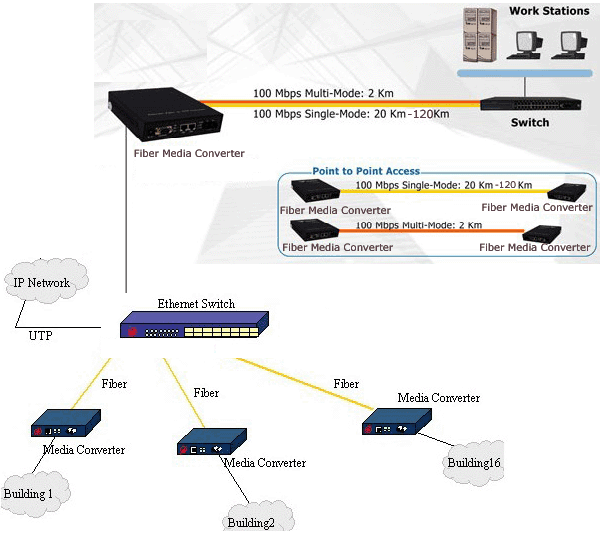
Applications
An Ethernet to Fiber Media Converter can also be used where there is high level of electromagnetic interference or EMI which is a common phenomenon found in industrial plants. This interference can cause corruption of data over copper-based ethernet links. Data transmitted over fiber optic cable however is completely immune to this type of noise. An Ethernet to Fiber Optic Converter therefore enables you to inter-connect your copper-ethernet devices over fiber ensuring optimal data transmission across the plant floor.
SNS Page


SOPTO Products
- Fiber Optic Transceiver Module
- High Speed Cable
- Fiber Optical Cable
- Fiber Optical Patch Cords
- Splitter CWDM DWDM
- PON Solution
- FTTH Box ODF Closure
- PCI-E Network Card
- Network Cables
- Fiber Optical Adapter
- Fiber Optical Attenuator
- Fiber Media Converter
- PDH Multiplexers
- Protocol Converter
- Digital Video Multiplexer
- Fiber Optical Tools
- Compatible
Related Products
Performance Feature
Converter Knowledge
Recommended
Common Problem of Fiber Media Converter
If you know the common problem of fiber media converter, you can check the problem out by yourself.
- Power light does not shine- Power failure
- LOS lights must have the following breakdown:
(A) There is a broken cable from the engine room to the client;
(B) SC pigtail is not plugged in Media Converter slots or has been disconnected.
3. Link light does not shine; the failure may be the following:
(A) Check whether the fiber optic lines breaker;
(B) Check whether the fiber line loss is too large, over a range of equipment receives;
(C) Check that the fiber optic interface is properly connected: local TX connects to remote RX; remote TX connects to local RX.
(D) Check whether the fiber optic connector is inserted into the device interface; whether the fiber patch cord matches with the device interface; device type matches with fiber; whether the equipment transmission length matches the distance.
4. Circuit Link light does not shine; the failure may be the following:
(A) Check whether the cable disconnection
(B) Check whether the connection type is match: network cards and routers and other devices use a crossover cable; switches, hubs, and other equipment use the straight line.
(C) Check whether the equipment transmission rate matches with the fiber media converter
5. The serious network packet loss possible failure may be the following:
(A) The electrical port of media converter does not match with the network device interface; or the duplex mode of both ends of the device interface mismatch.
(B) Twisted-pair and RJ-45 connector is broken. Detect them.
(C) Whether the optical fiber connection jumper alignment device interface, pigtails and jumpers and coupler type matches.
6. Fiber Media Converter can’t communicate after connecting both ends
(A) Fibres are reversed. The TX and RX are connected to the optical fiber reversely.
(B) RJ45 interface with external devices not connected properly (note that direct splicing)
Optical fiber interface (ceramic ferrule) do not match, this failure is mainly reflected in the transceiver 100M with optical mutual control function, such as APC ferrule pigtails received PC ferrule on the transceiver can’t communicate properly, but then non- the photoelectric interaction control transceiver has no effect.
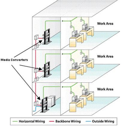
Media Converter working Area
7. Unstable transmission
(A) The attenuation of optical link may be too large. At this moment, we can test the optical power of the receiving end by using an optical meter. 1-2dB in the vicinity of the scope of the receiving sensitivity range can be substantially determines the optical path failure
(B) Switch connected to the fiber converter may be failure. At this moment, to replace the switch with PC, which means two media converters connect directly with the PC, both ends of the PING. We can basically judge the switch failure, when the unstable transmission phenomenon appears.
(C) The fiber converter may be failure. At this moment, we can connect both ends of fiber media converter with PC (not through a switch). If the PING is no problem, transfer a larger file (100M) above from one end to the other end, observing the speed. If the speed is very slow (more than 15 minutes when the file is less than 200M), we can basically judge that the fiber media converter is failure.
8. Communication for some time after the crash, that means it can’t communicate back to normal after re-starting
This phenomenon is generally caused by a switch to switch on all data received CRC error detection and length check, check out the error packets will be discarded, the correct packet will be forwarded out.
Some of the process error packets can’t be detected in the CRC error detection and length checksum this packet forwarding process will not be sent out, it will not be discarded, they will accumulate in the dynamic cache (buffer), can never be sent accumulation in wait until the buffer is full, it will cause the switch to crash the phenomenon.
Because re-start the fiber media converter or re-start switch can make communication back to normal, so users often think that the problem of the fiber media converter.
Related Knowledge:
General Architecture of a Protocol Converter
Applications of Ethernet Fiber Media Converter
Link Fault Pass Through (LLP. LFP) function for media converters