-

- Sopto Home
-

- Special Topic
-
- Patch Cord Knowledge
-
- Understanding Visual Inspection of Fiber Optic Connectors

Patch Cord Knowledge
- Fiber Optic Connector Ferrule Design
- Fiber Optic Connector Design
- E2000 to ST Fiber Patch Cable Overview
- Acceptable and Unacceptable Fiber Connector End-Face Finishes
- Using Wipes and Cleaning Cassettes to Clean Fiber Patch Cords
- Not-Too-Tight Mating of Fiber Optic Connectors
- Matching Gel and Oils Contamination about Fiber Optic Connectors
- The Effect of Improper Use of Fiber Optic Connectors
- Why Fiber Optic Connectors are Fragile?
SOPTO Special Topic
Certificate


Guarantee
Except products belongs to Bargain Shop section, all products are warranted by SOPTO only to purchasers for resale or for use in business or original equipment manufacturer, against defects in workmanship or materials under normal use (consumables, normal tear and wear excluded) for one year after date of purchase from SOPTO, unless otherwise stated...
Return Policies
Defective products will be accepted for exchange, at our discretion, within 14 days from receipt. Buyer might be requested to return the defective products to SOPTO for verification or authorized service location, as SOPTO designated, shipping costs prepaid. .....
Applications
 Fiber Patch Cords have a widely application. Where the need for the optical fiber connection, where you need fiber optic patch cords.
Testing Equipment
FTTX+ LAN
Optical Fiber CATV
Optical Communication System
Telecommunication
SNS Page


SOPTO Products
- Fiber Optic Transceiver Module
- High Speed Cable
- Fiber Optical Cable
- Fiber Optical Patch Cords
- Splitter CWDM DWDM
- PON Solution
- FTTH Box ODF Closure
- PCI-E Network Card
- Network Cables
- Fiber Optical Adapter
- Fiber Optical Attenuator
- Fiber Media Converter
- PDH Multiplexers
- Protocol Converter
- Digital Video Multiplexer
- Fiber Optical Tools
- Compatible
Related Products
Performance Feature
Good Water-proof
Low insertion loss;
low reflection loss;
Stability, good repeatability;
High-precision ceramic ferrule;
Compatible with NTT standard;
Precision Grinding and fully testing;
Compliance with international standards
Patch Cord Knowledge
Recommended
Understanding Visual Inspection of Fiber Optic Connectors
The inspection and interpretation of the results of polishing techniques and cleaning was subjective for many years. Visual inspection under a magnification scope or eye loupe was often the method used. In 2009 the IEC (International Electro-technical Commission) developed a standard for the inspection of fiber optic connectors (IEC 61300-3-35). The standard identifies areas of measurement and defines criteria for scratches and defects within those areas.
.jpg)
To properly interpret the results of the visual inspection one must first understand the areas of measurement as well as the size and quantity of scratches or defects within those areas being tested. For single mode connectors note the following measurement areas (zone) and pass/fail criteria.
Zone Diameter
- Core: 0 um to 25 um
- Cladding: 25 um to 120 um
- Adhesive: 120 um to 130 um
- Contact: 130 um to 250 um
Note 1: All data above assumes a 125 um cladding diameter.
Note 2: A defect is defined as existing entirely within the inner-most zone which is touches.
|
Zone Name |
Scratches |
Defects |
|
Core |
None |
None |
|
Cladding |
No Limit < 3um, None > 3um |
No Limit < 2um Five Defects from 2~5um None > 5um |
|
Adhesive |
No Limit |
No Limit |
|
Contact Area |
No Limit |
None > 10um |
Following are side by side images of a 400X magnified connector. The left image outlines the zone diameters and then identifies and measures the size of the imperfections. The image on the right is the magnified image only.
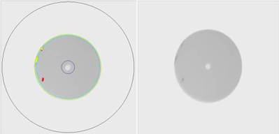
Rejected Side Images of a Connector
Result: Rejected
Reason: Three defects in the cladding zone. Those highlighted in red are over 5 um in diameter causing the failure condition.
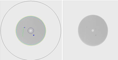
Accepted Side Images of a Connector
Result: Accepted
Reason: One fine scratch and two particles that are smaller than 5 um in the cladding zone.
As these examples show, minor defects or scratches are acceptable while major ones are not. The critical area is the core zone which may never have any imperfections. Minor defects in the cladding area are acceptable, and the contact area is of minor concern unless there are large defect.
There are a number of inspection products on the market. The more economical variety use a magnification process (200-400x) which generally give a good inspection of defects often created by cleaning or handling prior or after installation such as dust or smudging.
More robust products available include automated software that test to the IEC standard (Video Inspection Probe) removing the guesswork and subjectivity of the test. By utilizing an inspection probe system one can eliminate guesswork, improve network testing and documentation, and provide increased reliability of your network.
For more info, please browse our website. For purchasing fiber optic assembly products, please contact a Sopto representative by calling 86-755-36946668, or by sending an email to info@sopto.com.