-

- Sopto Home
-

- Special Topic
-
- Module Knowledge
-
- SFP Optical Module with DDM Applications
Module Knowledge
- Tips for Buying 10G XFP Transceivers
- XFP Transceivers for Telecommunications
- Three Types of Ethernet SFP Transceiver Modules Introduction
- Info about High Density CXP Optical Module
- Multipurpose CFP Optical Modules
- Info about CFP Management Interface
- SFP+ Transceivers Short Range Module Overview
- 3 Reasons Every Network Needs GLC-LH-SM Transceiver
- Is the GLC-SX-MM Transceiver Right for Your Switch?
SOPTO Special Topic
Certificate


Guarantee
Except products belongs to Bargain Shop section, all products are warranted by SOPTO only to purchasers for resale or for use in business or original equipment manufacturer, against defects in workmanship or materials under normal use (consumables, normal tear and wear excluded) for one year after date of purchase from SOPTO, unless otherwise stated...
Return Policies
Defective products will be accepted for exchange, at our discretion, within 14 days from receipt. Buyer might be requested to return the defective products to SOPTO for verification or authorized service location, as SOPTO designated, shipping costs prepaid. .....
Applications
 Fiber Optic Transceiver Modules can be applied to these occasions or fields.
Ethernet
IPTV
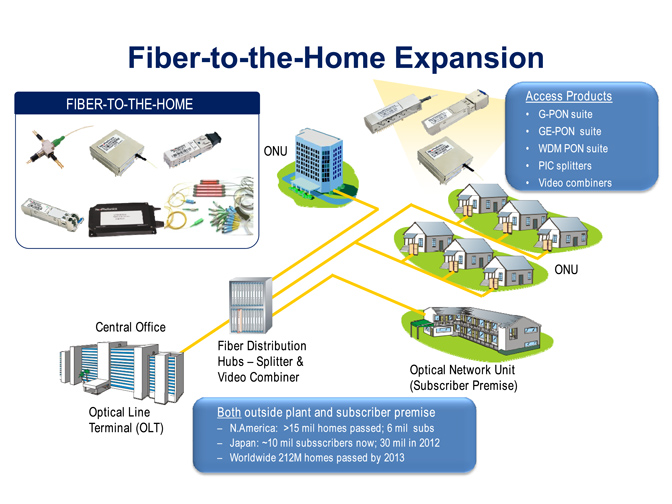
FTTX
Security
Video Monitor
SDH/SONET
Data Communication
Storage Area Networks
SNS Page


SOPTO Products
- Fiber Optic Transceiver Module
- High Speed Cable
- Fiber Optical Cable
- Fiber Optical Patch Cords
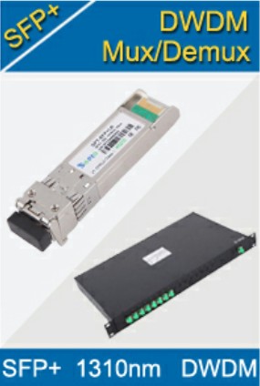
- Splitter CWDM DWDM
- PON Solution
- FTTH Box ODF Closure
- PCI-E Network Card
- Network Cables
- Fiber Optical Adapter
- Fiber Optical Attenuator
- Fiber Media Converter
- PDH Multiplexers
- Protocol Converter
- Digital Video Multiplexer
- Fiber Optical Tools
- Compatible
Related Products
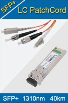
 10G SFP+ Transceiver
 40G QSFP+ Transceiver
Performance Feature
Stable
Low cost
Small size
Economic
Dust-proof
High speed
Hot-pluggable
Good EMI, EMC
Wide appliaction field
DDM function available
Long transmission distance
Good Anti-static performance
Module Knowledge
Recommended
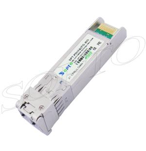
SFP Optical Module with DDM Applications
At present, the optical transceiver module in a variety of network types is more and more, increasingly high requirements. In order to meet the growing needs of the system, optical module is constantly moving towards standardization, miniaturization, and intelligence development. Intelligent SFP modules, digital diagnostic functions SFP optical module is a symbol of technological upgrading of various manufacturers products.
Using of intelligent optical modules, network management unit can real-time monitor transceiver module temperature, supply voltage, laser bias current, as well as transmit and receive optical power. The measurement of these parameters can help manage the unit to identify the location of the fiber link failure, simplify maintenance and improve system reliability. This article will describe how the optical module in digital diagnostic functions of positioning optical module system failure.
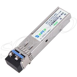
1.25G 1310nm 20km SFP Optical Transceiver with DDM
SFF-8472 MSA specification digital diagnostic functions and SFF-8472 details
The specification states that the circuit board inside the module detection and digital parameter signal. Then, after calibration or digital measurement results and calibration parameters, this information is stored in the memory structure of the standard, in order to read through the dual-cable serial interface.
The SFF-8472 to retain the original SFP / GBIC address A0h at the address mapping and address A2h added a 256-byte storage unit. Storage unit in addition to the parameter detection information, and also defines the alarm flag or alarm conditions, the state of each pin image, the limited number of control capabilities and user-writable storage unit.
The following are some of the information stored in the address space of the optical module with DDM function:
1) Real-time measurement of parameters – transmit optical power Tx_power received optical power Rx_power temperature the temp, the operating voltage Vcc, laser bias Laser the Bias;
2) The alarm or alarm – Tx_faul, the LOS measure the parameters of the alarm and the alarm flag;
3) Control flag – Tx_disable, Rate_select.
The application of digital diagnostic functions
Troubleshooting features in the optical transceiver system provides a means of performance monitoring, system management can help to predict the life of the transceiver module, the failure of the isolation system and to verify the compatibility of the module in the on-site installation.
Our optical module solved the intelligent SFP with H3C equipment compatibility issues, do fully compatible. Now available at major telecommunications network operators, CISCO, H3C, Huawei, ZTE and other mature applications.
Module Life prediction
This failure to predict that allows network managers to find potential link failure in the system performance affected.
Failure notice, the system administrator can business to switch to the backup link or replace a suspicious device, which in the case of non-stop services to repair the system.
Smart SFP provides a predictive laser deterioration of real-time parameter monitoring instruments.
The optical module within the optical power feedback control unit will control the output power in a stable level, but with the aging of the laser, the quantum efficiency of the laser will be reduced. The power control is achieved by increasing the laser bias current (Tx_Bias).
Therefore, we can predict the life of the laser through the monitoring of the laser bias current. This method can be a rough estimate of the life of the laser near the end.
Have a relationship because of the laser bias current and module temperature and the working voltage, so the need to consider when setting the bias current limit Temp and Vcc.
By real-time monitoring of transceiver module within the operating voltage and temperature, allowing the system administrator to find some potential problems:
1) The Vcc voltage is too high, will bring the breakdown of the CMOS device; the Vcc voltage is too low, the laser does not work properly.
2) Power consumption is too high will damage the receiver module.
3) The operating temperature is too high, will accelerate the aging of the device. In addition, through the monitoring of the received optical power lines and the performance of the remote transmitter can be monitored.
Fault location in the optical link, locate the fault location is critical to business fast loading. The fault isolation feature allows system administrators to quickly locate the position of a link failure. This feature can locate the fault line in the module; local modules or remote modules. By quickly locate the fault, reducing the repair time of system failure. Fault location, a comprehensive analysis of the status bits, pins and measurement parameters.
In short, digital diagnostic functions, you can locate the fault. Fault location on Tx_power Rx_power, Temp, and Vcc, Tx_Bias, warning and alarm status of a comprehensive analysis. Memory mirroring the state variables of the Tx to the Fault and Rx LOS (loss of signal) failure analysis plays an important role.
Another feature of digital diagnostic module compatibility verification
Compatibility verification is the analysis module of the working environment in line with the Data Sheet and the relevant standard compatible. Module performance can be guaranteed only in the work environment that is compatible.
In some cases, due to environmental parameters beyond the data sheet or the relevant standards, it will cause the module performance degradation, and thus transmission error. Working environment and the modules are not compatible:
1) The voltage beyond the specified scope;
2) Received optical power overload or below the receiver sensitivity;
3) The temperature exceeds the operating temperature range.
For more information, please browse our website or contact a Sopto representative by calling 86-755-36946668, or by sending an email to info@sopto.com.
You May Like:
 |
 |
 |
 |
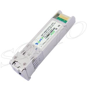
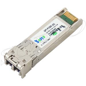
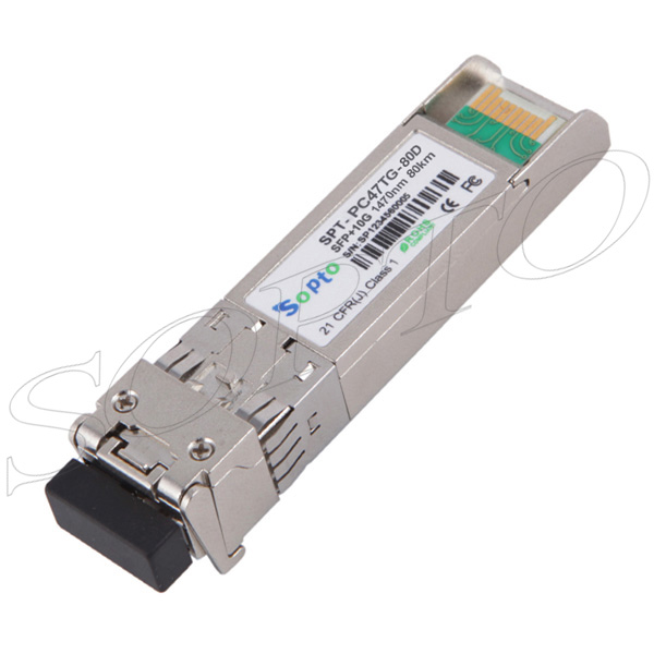
| 10G 1270/1330nm 40km WDM BIDI SFP+ Fiber Module | 6.25G 1310nm 10km SFP+ Transceiver | 10G 1260~1620nm 80km CWDM SFP+ Transceiver |
10G 1260~1620nm 80km DWDM SFP+ Optical Transceiver |