-

- Sopto Home
-

- Special Topic
-
- Module Knowledge
-
- Fiber Optical Module Installation
Module Knowledge
- Tips for Buying 10G XFP Transceivers
- XFP Transceivers for Telecommunications
- Three Types of Ethernet SFP Transceiver Modules Introduction
- Info about High Density CXP Optical Module
- Multipurpose CFP Optical Modules
- Info about CFP Management Interface
- SFP+ Transceivers Short Range Module Overview
- 3 Reasons Every Network Needs GLC-LH-SM Transceiver
- Is the GLC-SX-MM Transceiver Right for Your Switch?
SOPTO Special Topic
Certificate


Guarantee
Except products belongs to Bargain Shop section, all products are warranted by SOPTO only to purchasers for resale or for use in business or original equipment manufacturer, against defects in workmanship or materials under normal use (consumables, normal tear and wear excluded) for one year after date of purchase from SOPTO, unless otherwise stated...
Return Policies
Defective products will be accepted for exchange, at our discretion, within 14 days from receipt. Buyer might be requested to return the defective products to SOPTO for verification or authorized service location, as SOPTO designated, shipping costs prepaid. .....
Applications
 Fiber Optic Transceiver Modules can be applied to these occasions or fields.
Ethernet
IPTV
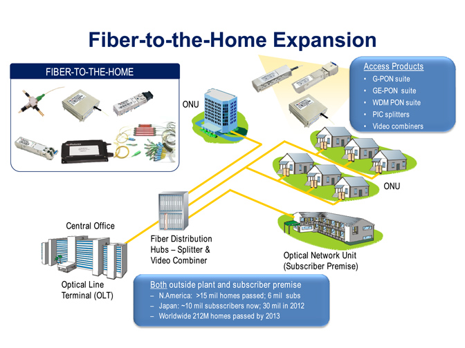
FTTX
Security
Video Monitor
SDH/SONET
Data Communication
Storage Area Networks
SNS Page


SOPTO Products
- Fiber Optic Transceiver Module
- High Speed Cable
- Fiber Optical Cable
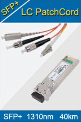
- Fiber Optical Patch Cords
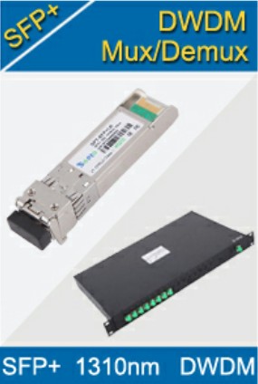
- Splitter CWDM DWDM
- PON Solution
- FTTH Box ODF Closure
- PCI-E Network Card
- Network Cables
- Fiber Optical Adapter
- Fiber Optical Attenuator
- Fiber Media Converter
- PDH Multiplexers
- Protocol Converter
- Digital Video Multiplexer
- Fiber Optical Tools
- Compatible
Related Products
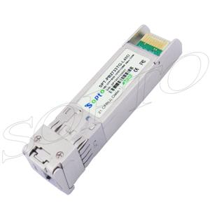
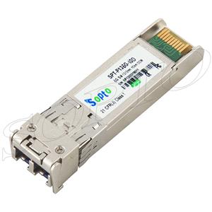
 10G SFP+ Transceiver
 40G QSFP+ Transceiver
Performance Feature
Stable
Low cost
Small size
Economic
Dust-proof
High speed
Hot-pluggable
Good EMI, EMC
Wide appliaction field
DDM function available
Long transmission distance
Good Anti-static performance
Module Knowledge
Recommended
Installation of Fiber Optic Transceiver Module
Necessary tools: ESD-preventive wrist strap
Take the SFP module as an example.
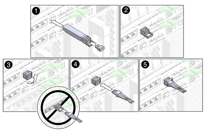
Complete these steps in order to install a SFP transceiver:
- Attach an ESD-preventive wrist strap to your wrist and to the ESD ground connector or a bare metal surface on your chassis.
- Remove the SFP Transceiver Module from its protective packaging.
- Check the label on the SFP transceiver body to verify that you have the correct model for your network.
- Find the send (TX) and receive (RX) markings that identify the top side of the SFP transceiver.
- Position the SFP transceiver in front of the socket opening.
- Insert the SFP transceiver into the socket until you feel the SFP Transceiver Module connector snap into place in the socket connector.
- Remove the dust plugs from the network interface cable LC connectors. Save the dust plugs for future use.
- Remove the dust plugs from the SFP transceiver optical bores.
- Immediately attach the network interface cable LC connector to the SFP transceiver.
- Connect the 1000BASE-T SFP transceivers to a copper network.
- Observe the port status LED:
- The LED turns green when the SFP transceiver and the target device have an established link.
- The LED turns amber while STP discovers the network topology and searches for loops. This process takes about 30 seconds, and then the LED turns green.
- If the LED is off, the target device might not be turned on, there might be a cable problem, or there might be a problem with the adapter installed in the target device. Refer to the Troubleshooting section of your switch hardware guide for solutions to cabling problems.
- Reconfigure and reboot the target device if necessary.
Installation Note:
- Do not remove the optical bore dust plugs until directed to do so later in the procedure.
- On some SFP transceivers, the TX and RX marking might be replaced by arrowheads that point from the SFP transceiver connector (transmit direction or TX) and toward the connector (receive direction or RX).
- Different devices have different SFP module socket configurations. Your device could have either a latch-up or a latch-down orientation. Ensure that you are installing the SFP transceiver in the correct orientation for your device. Refer to the hardware installation instructions that came with your device for more details.
- For optical SFP transceivers, before you remove the dust plugs and make any optical connections, observe these guidelines:
- Always keep the protective dust plugs on the unplugged fiber-optic cable connectors and the transceiver optical bores until you are ready to make a connection.
- Always inspect and clean the LC connector end-faces just before you make any connections. See the Required Tools section of this document for more information.
- Always grasp the LC connector housing to plug or unplug a fiber-optic cable.
Caution:
In order to comply with GR-1089 intra-building lightning immunity requirements, you must use grounded, shielded, twisted-pair Category 5 cabling.
Complete these steps in order to connect the transceivers to a copper network:
- Insert the Category 5 network cable RJ-45 connector into the SFP transceiver RJ-45 connector.
When you connect to a 1000BASE-T-compatible server, work station, or router, use four twisted-pair, straight-through Category 5 cabling for the SFP transceiver port. When you connect to a 1000BASE-T compatible switch or repeater, please use four twisted-pair, crossover Category 5 cabling.
- Insert the other end of the network cable into an RJ-45 connector on a 1000BASE-T-compatible target device.
You May Want to know:
You May Like:
 |
 |
 |
 |
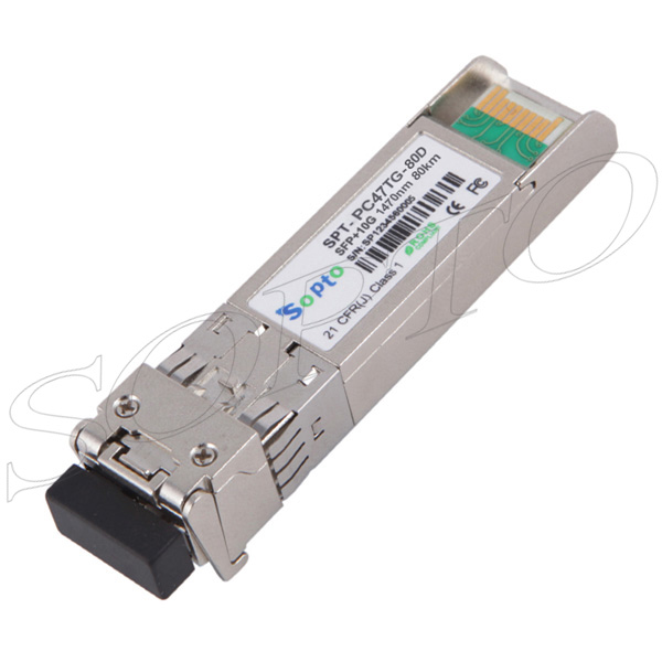
| 10G 1270/1330nm 40km WDM BIDI SFP+ Fiber Module | 6.25G 1310nm 10km SFP+ Transceiver | 10G 1260~1620nm 80km CWDM SFP+ Transceiver | 10G 1260~1620nm 80km DWDM SFP+ Optical Transceiver |