-

- Sopto Home
-

- Special Topic
-
- Module Knowledge
-
- Optical Module-Insertion Loss
Module Knowledge
- Tips for Buying 10G XFP Transceivers
- XFP Transceivers for Telecommunications
- Three Types of Ethernet SFP Transceiver Modules Introduction
- Info about High Density CXP Optical Module
- Multipurpose CFP Optical Modules
- Info about CFP Management Interface
- SFP+ Transceivers Short Range Module Overview
- 3 Reasons Every Network Needs GLC-LH-SM Transceiver
- Is the GLC-SX-MM Transceiver Right for Your Switch?
SOPTO Special Topic
Certificate


Guarantee
Except products belongs to Bargain Shop section, all products are warranted by SOPTO only to purchasers for resale or for use in business or original equipment manufacturer, against defects in workmanship or materials under normal use (consumables, normal tear and wear excluded) for one year after date of purchase from SOPTO, unless otherwise stated...
Return Policies
Defective products will be accepted for exchange, at our discretion, within 14 days from receipt. Buyer might be requested to return the defective products to SOPTO for verification or authorized service location, as SOPTO designated, shipping costs prepaid. .....
Applications
 Fiber Optic Transceiver Modules can be applied to these occasions or fields.
Ethernet
IPTV
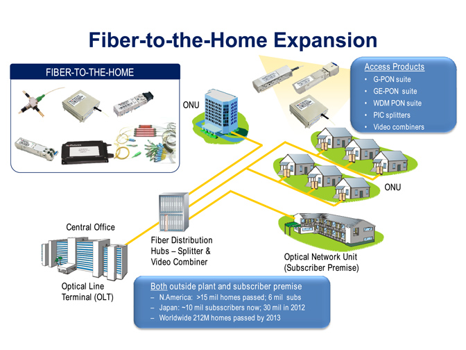
FTTX
Security
Video Monitor
SDH/SONET
Data Communication
Storage Area Networks
SNS Page


SOPTO Products
- Fiber Optic Transceiver Module
- High Speed Cable
- Fiber Optical Cable
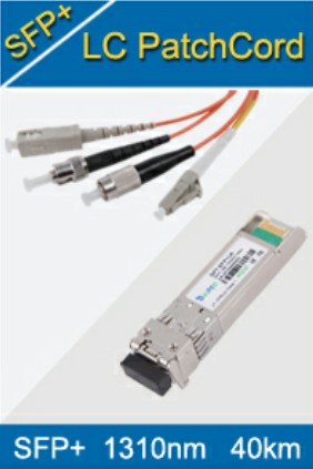
- Fiber Optical Patch Cords
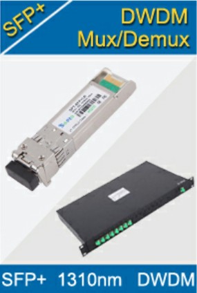
- Splitter CWDM DWDM
- PON Solution
- FTTH Box ODF Closure
- PCI-E Network Card
- Network Cables
- Fiber Optical Adapter
- Fiber Optical Attenuator
- Fiber Media Converter
- PDH Multiplexers
- Protocol Converter
- Digital Video Multiplexer
- Fiber Optical Tools
- Compatible
Related Products
 10G SFP+ Transceiver
 40G QSFP+ Transceiver
Performance Feature
Stable
Low cost
Small size
Economic
Dust-proof
High speed
Hot-pluggable
Good EMI, EMC
Wide appliaction field
DDM function available
Long transmission distance
Good Anti-static performance
Module Knowledge
Recommended
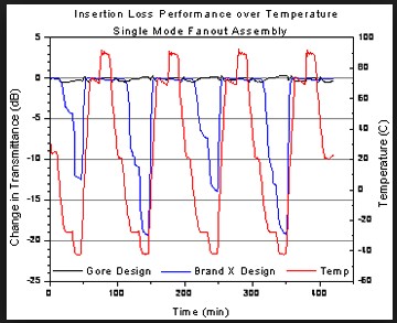
Understand Insertion Loss
In any fiber optic interconnection, some loss occurs. Insertion loss for a connector or splice is the difference in power that you see when you insert the device into the system. For example, take a length of fiber and measure the optical power through the fiber. Note the reading (P1). Now cut the fiber in half, terminate the fibers and connect them, and measure the power again. Note the second reading (P2). The difference between the first reading (P1) and the second (P2) is the insertion loss, or the loss of optical power that occurs when you insert the connector into the line. This is measured as:
IL (dB) = 10 Log10 (P2 / P1)
You must understand these two important things about insertion loss:
The specified insertion loss is for identical fibers.
If the core diameter (or the NA) of the side that transmits data is larger than the NA of the fiber that receives data, there is additional loss.
Ldia = 10 Log10 (diar/diat)2
LNA = 10 Log10 (NAr/NAt)2
where:
Ldia = Loss diameter
diar = diameter receive
diat = diameter transmit
LNA = Loss on optical fiber
Additional loss can occur from Fresnel reflections. These occur when two fibers are separated so that a discontinuity exists in the refractive index. For two glass fibers separated by an air gap, Fresnel reflections are 0.32 dB.
The loss depends on the launch.
The insertion loss depends on the launch, and receives conditions in the two fibers that are joined. In a short launch, you can overfill the fiber with optical energy carried in both the cladding and core. Over distance, this excess energy is lost until the fiber reaches a condition known as equilibrium mode distribution (EMD). In a long launch, the fiber has already reached EMD, so the excess energy is already stripped away and is not present at the connector.
Light that crosses the fiber-to-fiber junction of an interconnection can again overfill the fiber with excess cladding modes. These are quickly lost. This is the short-receive condition. If you measure the power output of a short-receive fiber, you can see extra energy. However, the extra energy is not propagated far. The reading is therefore incorrect. Similarly, if the length of the receive fiber is long enough to reach EMD, the insertion loss reading can be higher, but it reflects actual application conditions.
You can easily simulate EMD (long launch and receive). For this, you must wrap the fiber around a mandrel five times. This strips the cladding modes.
Related Knowledge:
Guess Products You May Like:
 |  |  |  |
| 10G 1260~1620nm 40km CWDM X2 ER Transceiver Module | 10/100/1000M 100m Copper SFP Fiber Optic Transceiver | 1000BASE-T Copper GBIC Transceiver | 1.25g 1310/1490nm 20km CSFP Fiber Optic Transceiver Module |