-

- Sopto Home
-

- Special Topic
-
- PCI-E Card Knowledge
-
- Structure of PCI Express Bus

PCI-E Card Knowledge
- Info about Network Interface Card Teaming
- How to Setup a Server with Multiple Network Interface Adapters?
- How to Reconnect an Internet Network Adapter for an Acer Aspire?
- 9 Things to Do When Your Internal Network Card Stops Working
- Ethernet Standards NIC for Home Networking
- What Is a Network Interface Adapter?
- How to Configure a Network Interface Card in Linux?
- How should Configure Your NIC for ISA and TMG?
- Recommended Network Card Configuration for Forefront UAG Servers
SOPTO Special Topic
Certificate


Guarantee
Except products belongs to Bargain Shop section, all products are warranted by SOPTO only to purchasers for resale or for use in business or original equipment manufacturer, against defects in workmanship or materials under normal use (consumables, normal tear and wear excluded) for one year after date of purchase from SOPTO, unless otherwise stated...
Return Policies
Defective products will be accepted for exchange, at our discretion, within 14 days from receipt. Buyer might be requested to return the defective products to SOPTO for verification or authorized service location, as SOPTO designated, shipping costs prepaid. .....
Applications
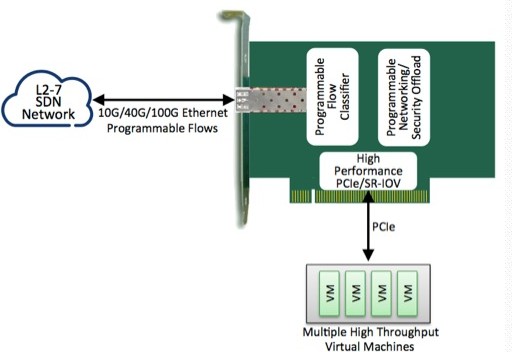
PCI-E NIC Cards provide redundant connectivity to ensure an uninterrupted network connection.
PCI-E NIC Cards are ideal for VM environments with multiple operating systems, requiring shared or dedicated NICs.
They are specially designed for desktop PC clients, servers, and workstations with few PCI Express slots available.
SNS Page


SOPTO Products
- Fiber Optic Transceiver Module
- High Speed Cable
- Fiber Optical Cable
- Fiber Optical Patch Cords
- Splitter CWDM DWDM
- PON Solution
- FTTH Box ODF Closure
- PCI-E Network Card
- Network Cables
- Fiber Optical Adapter
- Fiber Optical Attenuator
- Fiber Media Converter
- PDH Multiplexers
- Protocol Converter
- Digital Video Multiplexer
- Fiber Optical Tools
- Compatible
Related Products
Performance Feature
PCI-E Card Knowledge
Recommended
Structure of PCI Express Bus
Conceptually, the PCIe bus is like a high-speed serial replacement of the older PCI/PCI-X bus, an interconnect bus using shared address/data lines.
A key difference between PCIe bus and the older PCI is the bus topology. PCI uses a shared parallel bus architecture, where the PCI host and all devices share a common set of address/data/control lines. In contrast, PCIe is based on point-to-point topology, with separate serial links connecting every device to the root complex (host). Due to its shared bus topology, access to the older PCI bus is arbitrated (in the case of multiple masters), and limited to one master at a time, in a single direction.
Furthermore, the older PCI clocking scheme limits the bus clock to the slowest peripheral on the bus (regardless of the devices involved in the bus transaction). In contrast, a PCIe bus link supports full-duplex communication between any two endpoints, with no inherent limitation on concurrent access across multiple endpoints.
In terms of bus protocol, PCIe communication is encapsulated in packets. The work of packetizing and de-packetizing data and status-message traffic is handled by the transaction layer of the PCIe port (described later). Radical differences in electrical signaling and bus protocol require the use of a different mechanical form factor and expansion connectors (and thus, new motherboards and new adapter boards); PCI slots and PCIe slots are not interchangeable. At the software level, PCIe preserves backward compatibility with PCI; legacy PCI system software can detect and configure newer PCIe devices without explicit support for the PCIe standard, though PCIe's new features are inaccessible.
Architecture of the PCIE bus
The PCIe link between two devices can consist of anywhere from 1 to 32 lanes. In a multi-lane link, the packet data is striped across lanes, and peak data-throughput scales with the overall link width. The lane count is automatically negotiated during device initialization, and can be restricted by either endpoint. For example, a single-lane PCIe (×1) card can be inserted into a multi-lane slot (×4, ×8, etc.), and the initialization cycle auto-negotiates the highest mutually supported lane count. The link can dynamically down-configure the link to use fewer lanes, thus providing some measure of failure tolerance in the presence of bad or unreliable lanes.
The PCIe standard defines slots and connectors for multiple widths: ×1, ×4, ×8, ×16, ×32. This allows PCIe bus to serve both cost-sensitive applications where high throughput is not needed, as well as performance-critical applications such as 3D graphics, network (10 Gigabit Ethernet, multiport Gigabit Ethernet), and enterprise storage (SAS, Fibre Channel.)
As a point of reference, a PCI-X (133 MHz 64-bit) device and PCIe device using four lanes (×4), Gen1 speed have roughly the same peak transfer rate in a single-direction: 1064 MB/sec. The PCIe bus has the potential to perform better than the PCI-X bus in cases where multiple devices are transferring data communicating simultaneously, or if communication with the PCIe peripheral is bidirectional.
You May Want to Know:
Remove and reinstall a PCI expansion card