-

- Sopto Home
-

- Special Topic
-
- Fiber Optics knowledge
-
- Optical Power Loss in Fiber Access
Fiber Optics knowledge
- Maintained Methods of Fusion Splicer Parts
- How to Use the Fiber Optic Cleaver?
- What are Fixed Attenuators & Variable Attenuators?
- Deployable Fiber Optic Systems for Harsh Mining Environments
- Developing Miniature Fiber Optic Cable Has Become the Trend
- Fiber Optic Cleaning Procedures
- 6 Steps to Selecting a Fiber Optic Cable
- Signal Attenuation Introduction
- How Fiber Transmission Works?
SOPTO Special Topic
Certificate


Guarantee
Except products belongs to Bargain Shop section, all products are warranted by SOPTO only to purchasers for resale or for use in business or original equipment manufacturer, against defects in workmanship or materials under normal use (consumables, normal tear and wear excluded) for one year after date of purchase from SOPTO, unless otherwise stated...
Return Policies
Defective products will be accepted for exchange, at our discretion, within 14 days from receipt. Buyer might be requested to return the defective products to SOPTO for verification or authorized service location, as SOPTO designated, shipping costs prepaid. .....
Applications
Fiber Optis can be used in so many fields:
Data Storage Equipment
Interconnects,Networking
Gigabit Ethernet
FTTx, HDTV,CATV
Aerospace & Avionics
Data Transfer Tests
Network Equipment
Broadcast Automotive
Electronics,Sensing
Oil & Gas, Imaging
Outside Plant,Central Office
Harsh Environment
Data Transmission
Illumination,Institutions
Ship to Shore,Education
Simulation,Military,Space
Unmanned Aerial Vehicles
Semiconductor Equipment
Diagnostics & Troubleshooting
Premise Networks Carrier Networks
Independent Telecommunication Providers
SNS Page


SOPTO Products
- Fiber Optic Transceiver Module
- High Speed Cable
- Fiber Optical Cable
- Fiber Optical Patch Cords
- Splitter CWDM DWDM
- PON Solution
- FTTH Box ODF Closure
- PCI-E Network Card
- Network Cables
- Fiber Optical Adapter
- Fiber Optical Attenuator
- Fiber Media Converter
- PDH Multiplexers
- Protocol Converter
- Digital Video Multiplexer
- Fiber Optical Tools
- Compatible
Related Products
 10G SFP+ Transceiver
 40G QSFP+ Transceiver
Performance Feature
Fiber Optics knowledge
Recommended
Optical Power Loss in Fiber Access
The loss of power depends on the wavelength of the light and on the propagating material. For silica glass, the shorter wavelengths are attenuated the most (see Fig. 1). The lowest loss occurs at the 1550nm wavelength, which is commonly used for long-distance transmissions.
Transmission of light by fibre optics is not 100% efficient. There are several reasons for this including absorption by the core and cladding (caused by the presence of impurities) and the leaking of light from of the cladding. When light reflects off the cladding /core interface it actually travels for a short distance within the cladding before being reflected back. This leads to attenuation (signal reduction) by up to 2db/Km for a multi-mode fibre. For example, with this level of attenuation, if light travelled over 10kM of cable, only 10% of the signal would arrive at the following end.
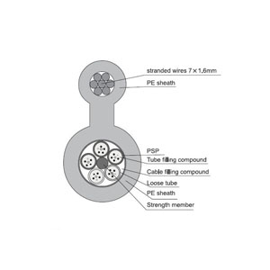
Outdoor Single Mode Figure 8 Aerial Hybrid Cable
The amount of attenuation for a given cable is also wavelength dependent. Figure 1 shows the attenuation profile for the two main types of fibre; multi-mode and single-mode cable (described in detail below). The absorption peak at 1000nm is caused by the peculiarities of single mode fibre while the peak at 1400nm is caused by traces of water remaining in the fibre as an impurity. Due to this water absorption peak there are two standard single-mode wavelengths in use, 1310nm and 1550nm. 1310nm has been a standard for many years, only now is there a trend towards using 1550nm brought about by the need to extend the distances between repeaters.
The loss of power in light in an optical fiber is measured in decibels (dB). Fiber optic cable specifications express cable loss as attenuation per 1km length as dB/km. This value is multiplied by the total length of the optical fiber in kilometers to determine the fiber's total loss in dB.
Optical fiber light loss is caused by a number of factors that can be categorized into extrinsic and intrinsic losses:
- Extrinsic
- Bending loss
- Splice and connector loss
- Intrinsic
- Loss inherent to fiber
- Loss resulting from fiber fabrication
- Fresnel reflection

Figure 1. Optical fiber operating wavelengths
Bend Loss
Bend loss occurs at fiber cable bends that are tighter than the cable's minimum bend radius. Bending loss can also occur on a smaller scale from such factors as:
- Sharp curves of the fiber core
- Displacements of a few millimeters or less, caused by buffer or jacket imperfections
- Poor installation practice
This light power loss, called microbending, can add up to a significant amount over a long distance.
Splice and Connector Loss
Splice loss occurs at all splice locations. Mechanical splices usually have the highest loss, commonly ranging from 0.2 to over 1.0 dB, depending on the type of splice. Fusion splices have lower losses, usually less than 0.1 dB. A loss of 0.05 dB or less is usually achieved with good equipment and an experienced splicing crew. High loss can be attributed to a number of factors, including:
- Poor cleave
- Misalignment of fiber cores
- An air gap
- Contamination
- Index-of-refraction mismatch
- Core diameter mismatch
Losses at fiber optic connectors commonly range from 0.25 to over 1.5 dB and depend greatly on the type of connector used. Other factors that contribute to the connection loss include:
- Dirt or contaminants on the connector (very common)
- Improper connector installation
- A damaged connector face
- Poor scribe (cleave)
- Mismatched fiber cores
- Misaligned fiber cores
- Index-of-refraction mismatch
Loss Inherent to Fiber
Light loss in a fiber that cannot be eliminated during the fabrication process is due to impurities in the glass and the absorption of light at the molecular level. Loss of light due to variations in optical density, composition, and molecular structure is called Rayleigh scattering. Rays of light encountering these variations and impurities are scattered in many directions and lost.
The absorption of light at the molecular level in a fiber is mainly due to contaminants in glass such as water molecules (OH-). The ingress of OUT molecules into an optical fiber is one of the main factors contributing to the fiber's increased attenuation in aging. Silica glass's (Si02) molecular resonance absorption also contributes to some light loss.
Figure 1 shows the net attenuation of a silica glass fiber and the three fiber operating windows at 850, 1310, and 1550 nm. For long-distance transmissions, 1310 or 1550nm windows are used. The 1550-nm window has slightly less attenuation than 1310nm. The 850nm communication is common in shorter-distance, lower cost installations.
Loss Resulting from Fiber Fabrication
Irregularities during the manufacturing process can result in the loss of light rays. For example, a 0.1 percent change in the core diameter can result in a 10dB loss per kilometer. Precision tolerance must be maintained throughout the manufacturing of the fiber to minimize losses.
Fresnel Reflection
Fresnel reflection occurs at any medium boundary where the refractive index changes, causing a portion of the incident light ray to be reflected back into the first medium. The fiber end is a good example of this occurrence. Light, traveling from air to the fiber core, is refracted into the core. However, some of the light, about 4 percent, is reflected back into the air. The amount being reflected can be estimated using the following formula shown in figure 2:
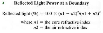
Figure 2. Reflected Light Power at a Boundary
At a fiber connector, the light reflected back can easily be seen with an optical time domain reflectometer (OTDR) trace. It appears as a large upward spike in the trace. This reflected light can cause problems if a laser is used and should be kept to a minimum.
The reflected light power can be reduced by using better connectors. Connectors with the "PC" (Physical Contact) or "APC" (Angle Physical Contact) designations are designed to minimize this reflection.
For more info, please browse our website. For purchasing fiber optic assembly products, please contact a Sopto representative by calling 86-755-36946668, or by sending an email to info@sopto.com.