-

- Sopto Home
-

- Special Topic
-
- Fiber Optics knowledge
-
- Fiber Optics’ Basic Types

Fiber Optics knowledge
- Maintained Methods of Fusion Splicer Parts
- How to Use the Fiber Optic Cleaver?
- What are Fixed Attenuators & Variable Attenuators?
- Deployable Fiber Optic Systems for Harsh Mining Environments
- Developing Miniature Fiber Optic Cable Has Become the Trend
- Fiber Optic Cleaning Procedures
- 6 Steps to Selecting a Fiber Optic Cable
- Signal Attenuation Introduction
- How Fiber Transmission Works?
SOPTO Special Topic
Certificate


Guarantee
Except products belongs to Bargain Shop section, all products are warranted by SOPTO only to purchasers for resale or for use in business or original equipment manufacturer, against defects in workmanship or materials under normal use (consumables, normal tear and wear excluded) for one year after date of purchase from SOPTO, unless otherwise stated...
Return Policies
Defective products will be accepted for exchange, at our discretion, within 14 days from receipt. Buyer might be requested to return the defective products to SOPTO for verification or authorized service location, as SOPTO designated, shipping costs prepaid. .....
Applications
Fiber Optis can be used in so many fields:
Data Storage Equipment
Interconnects,Networking
Gigabit Ethernet
FTTx, HDTV,CATV
Aerospace & Avionics
Data Transfer Tests
Network Equipment
Broadcast Automotive
Electronics,Sensing
Oil & Gas, Imaging
Outside Plant,Central Office
Harsh Environment
Data Transmission
Illumination,Institutions
Ship to Shore,Education
Simulation,Military,Space
Unmanned Aerial Vehicles
Semiconductor Equipment
Diagnostics & Troubleshooting
Premise Networks Carrier Networks
Independent Telecommunication Providers
SNS Page


SOPTO Products
- Fiber Optic Transceiver Module
- High Speed Cable
- Fiber Optical Cable
- Fiber Optical Patch Cords
- Splitter CWDM DWDM
- PON Solution
- FTTH Box ODF Closure
- PCI-E Network Card
- Network Cables
- Fiber Optical Adapter
- Fiber Optical Attenuator
- Fiber Media Converter
- PDH Multiplexers
- Protocol Converter
- Digital Video Multiplexer
- Fiber Optical Tools
- Compatible
Related Products
 10G SFP+ Transceiver
 40G QSFP+ Transceiver
Performance Feature
Fiber Optics knowledge
Recommended
Fiber Optics’ Basic Types
Understanding the characteristics of different fiber types aides in understanding the applications for which they are used. Operating a fiber optic system properly relies on knowing what type of fiber is being used and why. There are two basic types of fiber: multimode fiber and single-mode fiber. Multimode fiber is best designed for short transmission distances, and is suited for use in LAN systems and video surveillance. Single-mode fiber is best designed for longer transmission distances, making it suitable for long-distance telephony and multichannel television broadcast systems.
Multimode Fiber
Multimode fiber, the first to be manufactured and commercialized, simply refers to the fact that numerous modes or light rays are carried simultaneously through the waveguide. Modes result from the fact that light will only propagate in the fiber core at discrete angles within the cone of acceptance. This fiber type has a much larger core diameter, compared to single-mode fiber, allowing for the larger number of modes, and multimode fiber is easier to couple than single-mode optical fiber. Multimode fiber may be categorized as step-index or graded-index fiber.
Multimode Step-index Fiber
Figure1 shows how the principle of total internal reflection applies to multimode step-index fiber. Because the core's index of refraction is higher than the cladding's index of refraction, the light that enters at less than the critical angle is guided along the fiber.
Figure 1
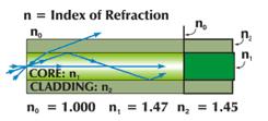
Total Internal Reflection in Multimode Step-index fiber
Three different lightwaves travel down the fiber. One mode travels straight down the center of the core. A second mode travels at a steep angle and bounces back and forth by total internal reflection. The third mode exceeds the critical angle and refracts into the cladding. Intuitively, it can be seen that the second mode travels a longer distance than the first mode, causing the two modes to arrive at separate times.
This disparity between arrival times of the different light rays is known as dispersion, and the result is a muddied signal at the receiving end. For a more detailed discussion of dispersion, see "Dispersion in Fiber Optic Systems" however, it is important to note that high dispersion is an unavoidable characteristic of multimode step-index fiber.
Multimode Graded-index Fiber
Graded-index refers to the fact that the refractive index of the core gradually decreases farther from the center of the core. The increased refraction in the center of the core slows the speed of some light rays, allowing all the light rays to reach the receiving end at approximately the same time, reducing dispersion. Figure 2 shows the principle of multimode graded-index fiber.
The core's central refractive index, nA, is greater than that of the outer core's refractive index, nB. As discussed earlier, the core's refractive index is parabolic, being higher at the center. As Figure2 shows, the light rays no longer follow straight lines; they follow a serpentine path being gradually bent back toward the center by the continuously declining refractive index. This reduces the arrival time disparity because all modes arrive at about the same time. The modes traveling in a straight line are in a higher refractive index, so they travel slower than the serpentine modes. These travel farther but move faster in the lower refractive index of the outer core region.
Figure 2
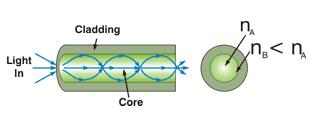
Multimode Graded-index Fiber
Single-mode Fiber
Single-mode fiber allows for a higher capacity to transmit information because it can retain the fidelity of each light pulse over longer distances, and it exhibits no dispersion caused by multiple modes. Single-mode fiber also enjoys lower fiber attenuation than multimode fiber. Thus, more information can be transmitted per unit of time.
Like multimode fiber, early single-mode fiber was generally characterized as step-index fiber meaning the refractive index of the fiber core is a step above that of the cladding rather than graduated as it is in graded-index fiber. Modern single-mode fibers have evolved into more complex designs such as matched clad, depressed clad and other exotic structures.
Single-mode fiber has disadvantages. The smaller core diameter makes coupling light into the core more difficult. The tolerances for single-mode connectors and splices are also much more demanding. Single-mode fiber has gone through a continuing evolution for several decades now. As a result, there are three basic classes of single-mode fiber used in modern telecommunications systems. The oldest and most widely deployed type is non-dispersion-shifted fiber(NDSF). These fibers were initially intended for use near 1310 nm.
Later, 1550 nm systems made NDSF fiber undesirable due to its very high dispersion at the 1550 nm wavelength. To address this shortcoming, fiber manufacturers developed, dispersion-shifted fiber(DSF), that moved the zero-dispersion point to the 1550 nm region. Years later, scientists would discover that while DSF worked extremely well with a single 1550 nm wavelength, it exhibits serious nonlinearities when multiple, closely-spaced wavelengths in the 1550 nm were transmitted in DWDM systems.
Recently, to address the problem of nonlinearities, a new class of fibers was introduced. These are classified as non-zero-dispersion-shifted fibers (NZ-DSF). The fiber is available in both positive and negative dispersion varieties and is rapidly becoming the fiber of choice in new fiber deployment.
Figure3
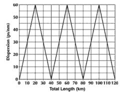
Dispersion for Alternating 20 km Lengths of (+D) NZ-DSF and (-D) NZ-DSF Fiber
One additional important variety of single-mode fiber is polarization-maintaining (PM) fiber. All other single-mode fibers discussed so far have been capable of carrying randomly polarized light. PM fiber is designed to propagate only one polarization of the input light. This is important for components such as external modulators that require a polarized light input.
Figure 4 shows the cross-section of a type of PM fiber. This fiber contains a feature not seen in other fiber types. Besides the core, there are two additional circles called stress rods. As their name implies, these stress rods create stress in the core of the fiber such that the transmission of only one polarization plane of light is favored. Single-mode fibers experience nonlinearities that can greatly affect system performance.
Figure4
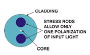
Cross-section of a type of PM fiber
For more high quality and low cost fiber optics, please contact SOPTO.
Related Knowledge:
Fiber Optics’ Manufacturing Processing
Optical Fiber Horizontal cabling Guideline
Comparison between Mechanical Splicing and Fusion Splicing