-

- Sopto Home
-

- Special Topic
-
- Fiber Optics knowledge
-
- Fiber Optic Installation Standard
Fiber Optics knowledge
- Maintained Methods of Fusion Splicer Parts
- How to Use the Fiber Optic Cleaver?
- What are Fixed Attenuators & Variable Attenuators?
- Deployable Fiber Optic Systems for Harsh Mining Environments
- Developing Miniature Fiber Optic Cable Has Become the Trend
- Fiber Optic Cleaning Procedures
- 6 Steps to Selecting a Fiber Optic Cable
- Signal Attenuation Introduction
- How Fiber Transmission Works?
SOPTO Special Topic
Certificate


Guarantee
Except products belongs to Bargain Shop section, all products are warranted by SOPTO only to purchasers for resale or for use in business or original equipment manufacturer, against defects in workmanship or materials under normal use (consumables, normal tear and wear excluded) for one year after date of purchase from SOPTO, unless otherwise stated...
Return Policies
Defective products will be accepted for exchange, at our discretion, within 14 days from receipt. Buyer might be requested to return the defective products to SOPTO for verification or authorized service location, as SOPTO designated, shipping costs prepaid. .....
Applications
Fiber Optis can be used in so many fields:
Data Storage Equipment
Interconnects,Networking
Gigabit Ethernet
FTTx, HDTV,CATV
Aerospace & Avionics
Data Transfer Tests
Network Equipment
Broadcast Automotive
Electronics,Sensing
Oil & Gas, Imaging
Outside Plant,Central Office
Harsh Environment
Data Transmission
Illumination,Institutions
Ship to Shore,Education
Simulation,Military,Space
Unmanned Aerial Vehicles
Semiconductor Equipment
Diagnostics & Troubleshooting
Premise Networks Carrier Networks
Independent Telecommunication Providers
SNS Page


SOPTO Products
- Fiber Optic Transceiver Module
- High Speed Cable
- Fiber Optical Cable
- Fiber Optical Patch Cords
- Splitter CWDM DWDM
- PON Solution
- FTTH Box ODF Closure
- PCI-E Network Card
- Network Cables
- Fiber Optical Adapter
- Fiber Optical Attenuator
- Fiber Media Converter
- PDH Multiplexers
- Protocol Converter
- Digital Video Multiplexer
- Fiber Optical Tools
- Compatible
Related Products
 10G SFP+ Transceiver
 40G QSFP+ Transceiver
Performance Feature
Fiber Optics knowledge
Recommended
Fiber Optic Installation StandardF
When installing optical cable, what you don't know could really hurt you or damage your cable. Familiarizing yourself with Standard 301 is a smart step to avoid such problems.
Up until a little over a year ago an installation standard for optical cable didn't exist. Yes, the NEC has covered optical cable for longer than that, but these requirements focus on fire safety and installation with electrical conductors; and not a whole lot more. That's all changed now. As of late 1998, a joint venture of the National Electrical Contractors Association (NECA) and the Fiber Optic Association approved and published ANSI/NEIS Standard 301. This standard is part of the American National Standards Institute (ANSI) National Electrical Installation Standards program.
If you're company installs optical cable, you'll need to become very familiar with the guidelines outlined in this standard. We'll go through some of the more important sections now to bring you up to speed.
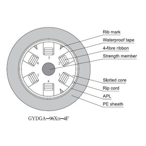
Slotted-Core Fiber Optic Cable with Aluminum
General Section. This section describes "procedures for installing, testing, and commissioning of systems that use fiber-optic cables and related components to carry signals for telecommunications, control, and similar purposes." The intent of the standard is to define "a minimum level of quality for fiber-optic cable installations."
Cable Installation. These sections outline proper installation of optical cable. The first requirement is "all fiber-optic cables should be installed in accordance with their listings and manufacturers' instructions." Although this seems obvious, one section details how cables must be supported:
All optical cables shall be securely supported, and shall have the supports spaced closely enough that there will be no excessive force placed on the cable. In general, horizontal indoor cables shall be supported at intervals not exceeding 3 ft (91 cm). Supports may be placed up to 5 ft (1.52 m) apart for armored cables, or cables over 1/2 in. (1.3 cm) in diameter. Cables directly buried require no additional support. Cables in raceways are considered to be adequately supported by the raceway.
Another section addresses the tightness of supports. The section reads: All straps or supports placed on fiber-optic cables shall be tight enough to hold the cable securely, but shall not be tight enough to substantially deform the shape of the cable. When optical cables are squeezed out of shape, unacceptable forces are placed on the fibers, which frequently result in microbends, microcracking, or even broken fibers. Where possible, rounded or padded supports shall be used. Cable ties shall not be cinched too tightly, and shall have the free tab cut off, to prevent over tightening in the future.
Notice that with power wiring we are seldom concerned with supports being over tightened. But with data cables (not only fiber), over tightening is a frequent source of cable damage you must avoid.
The standard also lists general rules to be followed when pulling cables into place. After mentioning that manufacturer's instructions take pre-eminence, the following rules are given:
• When pulling optical cables into conduits, cable trays, or raceways, the strength member(s) of the cable shall bear all or nearly all of the pulling force. Cable jackets shall not be directly pulled unless designed for the purpose, or unless the run is very short and requires a minimal pulling force. Optical cables shall not be pulled into place by applying tension directly to the fibers (pulling the fibers).
• Optical cables shall be attached to a pulling line only by methods recommended by the manufacturer of the cable.
• Unless stated otherwise by the cable manufacturer, the maximum pulling tensions used for optical cables shall be 300 lb. (136 kG) for multi-fiber indoor cable and 600 lb. (273 kG) for outdoor cable. The pulling force shall be uniform and consistent; cables shall not be jerked.
• Cable pulling shall be done by hand, except when tension meters, tension-controlled, or breakaway swivels are employed.
• When powered pulling equipment is used to install optical cable, tension monitoring equipment or breakaway swivels shall be used. Swivels shall be used when pulling optical cables into conduits. Exceptions shall be made to this requirement only for very short runs, which require a minimum pulling force.
• Continuous cable pulls shall be used whenever possible, avoiding splice points.
• Boxes used with optical cables shall be designed for the purpose, and shall be equipped with cable supports. Pull boxes shall be sized so that no cables in the box shall be tightly bent.
• A length of free cable shall be provided at each end of a cable pull. Loops of cable (commonly called service loops) shall be provided at all intermediate pulling points, such as in manholes and pull boxes. The cables' minimum bending radii shall not be violated.
• When pulls are accomplished in two or more stages, and spare cable must be unreeled, it shall be configured in large figure-8 on a safe, flat surface, such as the ground or a clean floor.
• When pulling fiber-optic cable through nonmetallic raceways (or nonmetallic 90 degrees elbows) with rope, maximum speed through a duct shall be about 3ft (91 cm) per second. If mule tape is used, the top speed shall be 9ft (274 cm) per second. The intent of this requirement is that the nonmetallic conduit or elbows will not be cut or grooved by the pulling process.
• When underground raceways containing optical cables enter a structure, the raceway shall be sealed to prevent the entry of gasses into the structure. The entry of outside plant cables into a structure may require special fire safety considerations.
Safety precautions. We were quite pleased to find this section made it into the final standard without much revision; and its final form was by no means certain until the standards committee took several votes.) With two primary safety hazards associated with optical fiber systems, the more commonly talked about hazard is retina damage; due to looking into the ends of live fibers. In real life, however, this is a rare situation.
Few fiber systems have power enough to cause eye damage (cable TV systems being the exception), and most broken fiber ends will diffuse the light passing through them anyway. Nonetheless, this is a legitimate concern.
The second concern, however, is far more serious. This is the hazard posed by broken pieces of fiber. These are essentially small glass needles, and can be quite dangerous: Painful when stuck in the skin as a splinter, they are potentially life-threatening if ingested. Hence the safety requirements of this section of the standard:
• Live optical fiber ends (live fibers are those with signals being sent through them) shall not be inspected by technicians; fibers shall be dark (no signal being transmitted) when inspected. Care shall be taken in verifying that the fibers are not live, since the light used in the majority of optical systems is not visible to the human eye.
• If there is a risk of fibers being inspected live; especially when the system light source is a laser, all technicians working on the system shall wear protective glasses, which have infrared filtering.
• Fiber-optic work areas shall be clean, organized, well lit, and shall be equipped with a bottle or other suitable container for broken or stray fiber pieces.
• No food, drink, or smoking shall be allowed in areas where fiber-optic cables are spliced or terminated, or in any area where bare fibers are being handled.
• Technicians making fiber terminations or splices or working with bare fiber shall be supplied with double-sided tape, or some other effective means, for picking up broken or stray pieces of fiber. All work areas where bare fiber may exist shall be repeatedly and consistently cleared of all bare fiber pieces. All bare fiber pieces shall be disposed of so that they cannot escape and cause a hazard. (For example, bare fibers should be sealed in some type of bottle or container before being dumped into a wastebasket.)
• All technicians working on bare fiber shall thoroughly wash their hands immediately when leaving the work area. They shall also check their clothing, and pat themselves with clean tape to remove any stray pieces of bare fiber.
Documentation. The installation of optical cable relies heavily on testing and documentation. For most electrical installations, the only testing done is flipping on the light switch. But for data, every run of cable must be separately tested and the results permanently documented.
This is not especially difficult, but it does require time and effort. More importantly, it requires a change of mind-set for workers that cut their teeth on power wiring. The requirements of this section are as follows:
All optical test results shall be thoroughly and accurately documented, and copies of the test results saved in a permanent form (typically in both hard copy and on computer disk). In general, documentation of test results shall include the following information:
• Cable type and length
• Splice and termination points
• Fiber type and size
• Connector types
• Splice types
• Cable paths
• End-to-end losses of completed transmitter-to-receiver links
• (Optional) End-to-end losses of individual fiber links The following tests shall be performed on all fiber-optic cable installations:
• Continuity testing upon delivery of optical cables to the site of installation
• End-to-end loss testing for each complete transmitter-to-receiver link
• End-to-end loss testing on each individual link in the system, if transmitter-to-receiver loss is beyond acceptable limits.
In addition, other types of testing may be required for certain types of installations. Long runs shall be tested with an optical time domain reflectometer, and permanent copies shall be made of all OTDR traces. All such trace copies shall be clearly marked as to the date taken, and details of the cable and fiber runs.
For purchasing more fiber optics’ information, please contact a Sopto representative by calling 86-755-36946668, or by sending an email to info@sopto.com.