-

- Sopto Home
-

- Special Topic
-
- Fiber Optics knowledge
-
- Fabrication of Optical Fibers

Fiber Optics knowledge
- Maintained Methods of Fusion Splicer Parts
- How to Use the Fiber Optic Cleaver?
- What are Fixed Attenuators & Variable Attenuators?
- Deployable Fiber Optic Systems for Harsh Mining Environments
- Developing Miniature Fiber Optic Cable Has Become the Trend
- Fiber Optic Cleaning Procedures
- 6 Steps to Selecting a Fiber Optic Cable
- Signal Attenuation Introduction
- How Fiber Transmission Works?
SOPTO Special Topic
Certificate


Guarantee
Except products belongs to Bargain Shop section, all products are warranted by SOPTO only to purchasers for resale or for use in business or original equipment manufacturer, against defects in workmanship or materials under normal use (consumables, normal tear and wear excluded) for one year after date of purchase from SOPTO, unless otherwise stated...
Return Policies
Defective products will be accepted for exchange, at our discretion, within 14 days from receipt. Buyer might be requested to return the defective products to SOPTO for verification or authorized service location, as SOPTO designated, shipping costs prepaid. .....
Applications
Fiber Optis can be used in so many fields:
Data Storage Equipment
Interconnects,Networking
Gigabit Ethernet
FTTx, HDTV,CATV
Aerospace & Avionics
Data Transfer Tests
Network Equipment
Broadcast Automotive
Electronics,Sensing
Oil & Gas, Imaging
Outside Plant,Central Office
Harsh Environment
Data Transmission
Illumination,Institutions
Ship to Shore,Education
Simulation,Military,Space
Unmanned Aerial Vehicles
Semiconductor Equipment
Diagnostics & Troubleshooting
Premise Networks Carrier Networks
Independent Telecommunication Providers
SNS Page


SOPTO Products
- Fiber Optic Transceiver Module
- High Speed Cable
- Fiber Optical Cable
- Fiber Optical Patch Cords
- Splitter CWDM DWDM
- PON Solution
- FTTH Box ODF Closure
- PCI-E Network Card
- Network Cables
- Fiber Optical Adapter
- Fiber Optical Attenuator
- Fiber Media Converter
- PDH Multiplexers
- Protocol Converter
- Digital Video Multiplexer
- Fiber Optical Tools
- Compatible
Related Products
 10G SFP+ Transceiver
 40G QSFP+ Transceiver
Performance Feature
Fiber Optics knowledge
Recommended
Fabrication of Optical Fibers
Basically, fiber manufacturers use two methods to fabricate multimode and single mode glass fibers. One method is vapor phase oxidation, and the other method is direct-melt process. In vapor phase oxidation, gaseous metal halide compounds, dopant material, and oxygen are oxidized (burned) to form a white silica powder (SiO2). Manufacturers call SiO2 the soot.
Manufacturers deposit the soot on the surface of a glass substrate (mandrel) or inside a hollow tube by one of the following three methods:
- Outside Vapor Phase Oxidation (OVPO)
- Inside Vapor Phase Oxidation (IVPO)
- Vapor Phase Axial Deposition (VAD)
The soot forms the core and cladding material of the preform. The refractive index of each layer of soot is changed by varying the amount of dopant material being oxidized. Figures1, 2, and 3 illustrate the different vapor phase oxidation preform preparation methods.
Figure1
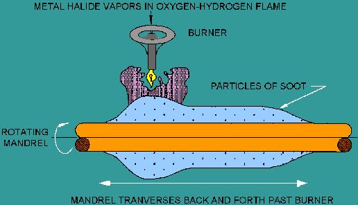
OVPO preform preparation
Figure2
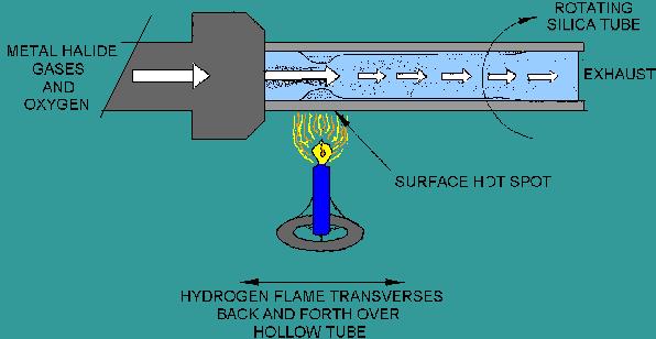
IVPO preform preparation
Figure3
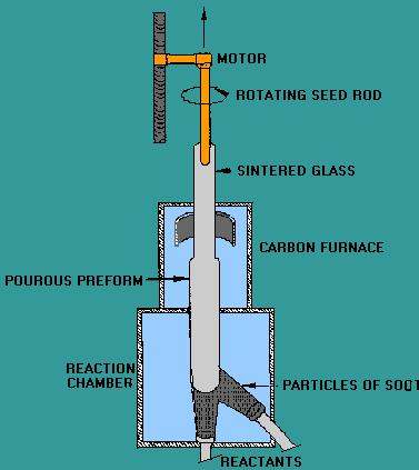
VAD preform preparation
During vapor phase oxidation, the mandrel or tube continuously moves from side to side and rotates while soot particles are deposited on the surface. This process forms cylindrical layers of soot on the surface of the mandrel or inside the hollow tube. This deposited material is transformed into a solid glass preform by heating the porous material (without melting).
The solid preform is then drawn or pulled into an optical fiber by a process called fiber drawing.
The fiber drawing process begins by feeding the glass preform into the drawing furnace. The drawing furnace softens the end of the preform to the melting point. Manufacturers then pull the softened preform into a thin glass filament (glass fiber). To protect the bare fiber from contaminants, manufacturers add an acrylate coating in the draw process. The coating protects the bare fiber from contaminants such as atmospheric dust and water vapor.
Figure 4 illustrates the process of drawing an optical fiber from the preform.
Figure 4
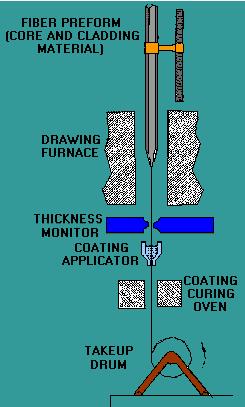
Fiber drawing process
In the direct-melt process, multicomponent glass rods form the fiber structure. Rods of multicomponent glass combine in a molten state to form the fiber core and cladding. The double-crucible method is the most common direct-melt process. The double-crucible method combines the molten rods into a single preform using two concentric crucibles.
Optical fibers are drawn from this molten glass using a similar fiber drawing process as in vapor phase oxidation. Figure 5 illustrates the double-crucible drawing process.
Figure 5
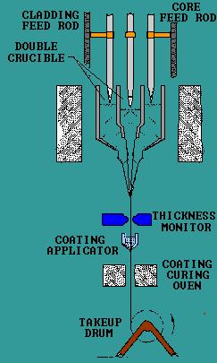
Double-crucible fiber drawing process
For more high quality and low cost fiber optics, please contact SOPTO.
Related Knowledge:
What is a Fiber Optic Patch Panel?
Optical Fiber Horizontal cabling Guideline
China FTTH fiber optic splicing best method
Optical Fiber Cable General Cabling Guidelines