-

- Sopto Home
-

- Special Topic
-
- Fiber Optics knowledge
-
- Coupling Losses of Imperfect Fiber Joints
Fiber Optics knowledge
- Maintained Methods of Fusion Splicer Parts
- How to Use the Fiber Optic Cleaver?
- What are Fixed Attenuators & Variable Attenuators?
- Deployable Fiber Optic Systems for Harsh Mining Environments
- Developing Miniature Fiber Optic Cable Has Become the Trend
- Fiber Optic Cleaning Procedures
- 6 Steps to Selecting a Fiber Optic Cable
- Signal Attenuation Introduction
- How Fiber Transmission Works?
SOPTO Special Topic
Certificate


Guarantee
Except products belongs to Bargain Shop section, all products are warranted by SOPTO only to purchasers for resale or for use in business or original equipment manufacturer, against defects in workmanship or materials under normal use (consumables, normal tear and wear excluded) for one year after date of purchase from SOPTO, unless otherwise stated...
Return Policies
Defective products will be accepted for exchange, at our discretion, within 14 days from receipt. Buyer might be requested to return the defective products to SOPTO for verification or authorized service location, as SOPTO designated, shipping costs prepaid. .....
Applications
Fiber Optis can be used in so many fields:
Data Storage Equipment
Interconnects,Networking
Gigabit Ethernet
FTTx, HDTV,CATV
Aerospace & Avionics
Data Transfer Tests
Network Equipment
Broadcast Automotive
Electronics,Sensing
Oil & Gas, Imaging
Outside Plant,Central Office
Harsh Environment
Data Transmission
Illumination,Institutions
Ship to Shore,Education
Simulation,Military,Space
Unmanned Aerial Vehicles
Semiconductor Equipment
Diagnostics & Troubleshooting
Premise Networks Carrier Networks
Independent Telecommunication Providers
SNS Page


SOPTO Products
- Fiber Optic Transceiver Module
- High Speed Cable
- Fiber Optical Cable
- Fiber Optical Patch Cords
- Splitter CWDM DWDM
- PON Solution
- FTTH Box ODF Closure
- PCI-E Network Card
- Network Cables
- Fiber Optical Adapter
- Fiber Optical Attenuator
- Fiber Media Converter
- PDH Multiplexers
- Protocol Converter
- Digital Video Multiplexer
- Fiber Optical Tools
- Compatible
Related Products
 10G SFP+ Transceiver
 40G QSFP+ Transceiver
Performance Feature
Fiber Optics knowledge
Recommended
Coupling Losses of Imperfect Fiber Joints
A frequently asked question is how large will be coupling losses e.g. at a mechanical splice, when there is some kind of imperfection, for example
- a parallel offset of the fiber cores
- a deviation between the fiber axis directions
- a mismatch of core sizes
- an air gap between the fiber ends
It turns out that some of the answers are quite different for single-mode and multimode fibers.
It is relatively easy to calculate coupling losses for single-mode fibers. Essentially, the guided mode from the first fiber (the input) creates some amplitude profile in the second fiber, which may be somewhat displaced, for example, due to an imperfect splice. One can now calculate the coupling efficiency as an overlap integral between that amplitude profile and that of the guided mode of the second fiber. (Numerical beam propagation is not required.)
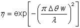
For the case of different mode radii and some parallel offset, one can use the equation which shown below:
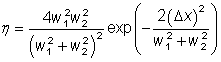
Equation of different mode radii and some parallel offset
A similar equation can be used for an angular mismatch:
Angular mismatch equation
This shows that the angular alignment is more critical for single-mode fibers with large mode area. For standard mode areas, the angular alignment is usually easier to achieve than the position alignment.
The following figures are based on the equations above.
.png)
Figure 1: Insertion loss at a mechanical splice for single-mode fibers due to a mismatch of mode radii.
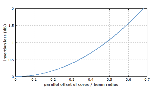
Figure 2: Insertion loss at a mechanical splice for single-mode fibers due to a parallel offset of the cores.
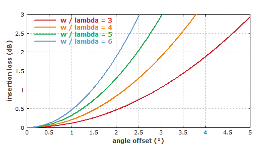
Figure 3: Insertion loss at a mechanical splice for single-mode fibers due to an error of the angle, as might result from a non-perpendicular cleave. This has been calculated for different ratios of the mode radius to the wavelength.
Concerning angle-cleaved fiber ends, it is often of interest how large the cleave angle needs to be to avoid significant reflection into the core mode. The equation can well be used for that; one simply has to keep in mind that the angular deviation of the reflected beam is twice the cleave angle. As an example, a fiber with a standard mode area of 100 μm2, having w = 5.64 μm, needs a cleave angle of at least 7.4° in order to have a backreflection below 10−4, i.e., at least 40 dB return loss, at 1.5 μm wavelength. For a large mode area fiber with 1000 μm2, 2.3° would be sufficient. Note that longer wavelengths require larger cleave angles, as they lead to large beam divergence.
It is interesting to consider some more details. For example, does it matter for the losses from which fiber the input light comes, if the mode sizes are different? According to the equation above, it doesn't. This is true, although it might be surprising: one could imagine that going from a smaller core to a larger one causes lower losses than in the other direction. Note, however, that the smaller mode has a larger beam divergence, i.e., a wider field distribution in spatial Fourier space, and that is too much for the other fiber with larger mode. So the fraction of power lost at the splice really doesn't depend on the direction; only the lost light is differently distributed over the cladding modes.
One could imagine that when going from a smaller-mode fiber to one with a larger mode, one could avoid the coupling losses if the second fiber has the same NA despite the larger core. (It might still be single-mode if the V number is low enough.) After all, the angular range should be limited only by the NA. However, this expectation is wrong; a mismatch of mode sizes inevitably causes coupling losses, if both fibers are single-mode.
For multimode fibers, the losses cannot be specified as a single number: they are generally mode-dependent. This means that for arbitrary input light fields, the resulting overall loss will depend on how the power is distributed over the modes. One can imagine, for example, that light is launched into low-order modes only with a laser, and that this leads to low splice losses. If one then strongly bends the fiber before the splice, the light might be redistributed into higher-order modes, and the splice losses get larger.
As an example for coupling losses, consider a perfect mechanical splice between two step-index multimode fibers with equal NA of 0.2 (calculated from the maximum index difference), but the first fiber has a core diameter of 62.5μm and the second one only 50μm. We can calculate each mode of the first fiber, sum up the modulus squared of its’ overlap integral with all modes of the second fiber, and in that way obtain its coupling loss. (Alternatively, one may use a numerically simulated beam propagation, but this takes more computation time and is tentatively less precise.) Figure 4 shows the losses versus the m value of the modes. These losses are highest for low m but high loss values.
Figure 4: Losses versus the m value of the modes
Mode-dependent coupling losses at a multimode fiber splice. The horizontal coordinate reflects the m value of each mode, while the color depends on loss.
One may be surprised that the coupling loss for the LP14,3 mode is so high – about 10 dB, far higher than according to the ratio of mode areas (1.94 dB). However, that mode has a high portion of its power outside the radius of 25μm, and in addition its intensity distribution in Fourier space reaches quite far out. The calculated result has been confirmed with a calculation based on numerical beam propagation, which is a quite independent check.
If one exchanges the two fibers, i.e., has an input coming from the smaller core, the coupling losses for all modes get much smaller:
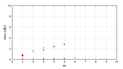
Figure 5: Same as Figure 3, but with the light input to the fiber with the smaller core.
So for multimode fibers, other than for single-mode fibers, the coupling losses are substantially smaller when coming from the fiber with the smaller core. However, for some modes these losses are still substantial – for example, 2.8 dB for the LP55 mode. Numerical beam propagation confirmed that result. It shows that the field, when it gets into the fiber with larger core, starts to expand, and that expansion is later on not fully stopped at the new core/cladding boundary. This shows that not every field distribution within the core and with limited angular content can be well matched by the guided modes.
Such effects are less pronounced for fibers having many modes. Basically, one has to be aware that the modes of the smaller core span a mathematical space which is not a subspace of that for a larger core.
Claim: The info above is reprinted from:
http://www.rp-photonics.com/passive_fiber_optics6.html
For more info, please browse our website.