-

- Sopto Home
-

- Special Topic
-
- Converter Knowledge
-
- How Fiber Media Converter Works?
Converter Knowledge
- Form Factors and Application of Ethernet Media Converter
- Ethernet over 4 E1 Converter Brief Introduction
- What is the Difference between RS232 and RS485 Serial Interfaces
- What is the Difference between RS232 and RS485 Serial Interfaces
- How to Convert an Analog Telephone to VoIP Protocol?
- How to Find the Internet Protocol Address and Media Access Contr
- How to Convert from Fast Ethernet to Fiber Optics?
- How to Connect a Fiber Converter?
- How to Convert Ethernet to Fiber Media Converters?
SOPTO Special Topic
Certificate


Guarantee
Except products belongs to Bargain Shop section, all products are warranted by SOPTO only to purchasers for resale or for use in business or original equipment manufacturer, against defects in workmanship or materials under normal use (consumables, normal tear and wear excluded) for one year after date of purchase from SOPTO, unless otherwise stated...
Return Policies
Defective products will be accepted for exchange, at our discretion, within 14 days from receipt. Buyer might be requested to return the defective products to SOPTO for verification or authorized service location, as SOPTO designated, shipping costs prepaid. .....
Applications
An Ethernet to Fiber Media Converter can also be used where there is high level of electromagnetic interference or EMI which is a common phenomenon found in industrial plants. This interference can cause corruption of data over copper-based ethernet links. Data transmitted over fiber optic cable however is completely immune to this type of noise. An Ethernet to Fiber Optic Converter therefore enables you to inter-connect your copper-ethernet devices over fiber ensuring optimal data transmission across the plant floor.
SNS Page


SOPTO Products
- Fiber Optic Transceiver Module
- High Speed Cable
- Fiber Optical Cable
- Fiber Optical Patch Cords
- Splitter CWDM DWDM
- PON Solution
- FTTH Box ODF Closure
- PCI-E Network Card
- Network Cables
- Fiber Optical Adapter
- Fiber Optical Attenuator
- Fiber Media Converter
- PDH Multiplexers
- Protocol Converter
- Digital Video Multiplexer
- Fiber Optical Tools
- Compatible
Related Products
Performance Feature
Converter Knowledge
Recommended
How Fiber Media Converter Works?
How Fiber Optic Media Converters Works is a questions that has been driven in recent years by the factor has become apparent that fiber optics are steadily replacing copper wire as an appropriate means of communication signal transmission. They span the long distances between local phone systems as well as providing the backbone for many network systems. Other system users include cable television services, university campuses, office buildings, industrial plants, and electric utility companies.
A fiber optic system is similar to the copper wire system that fiber optics is replacing. The difference is that fiber optics use light pulses to transmit information down fiber lines instead of using electronic pulses to transmit information down copper lines. Looking at the components in a fiber optic chain, we will give a better understanding of how the system works in conjunction with wire based systems.
The following diagrams show how you can take a multitude of applications and transport them via a fiber optic cable (single mode or multi-mode) to another location up to 80 km away.
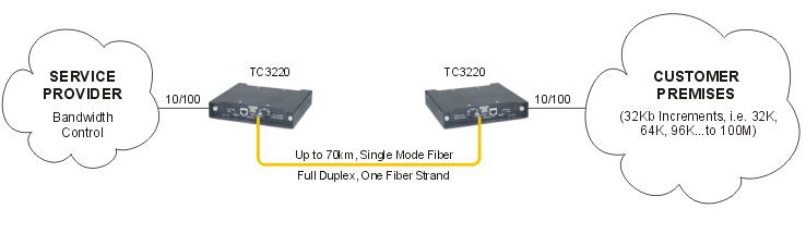
Fiber Media Converter Typical Applications
At one end of the system is a transmitter. This is the place of origin for information coming on to fiber optic lines. The transmitter accepts coded electronic pulse information coming from copper wire. It then processes and translates that information into equivalently coded light pulses. A light-emitting diode (LED) or an injection-laser diode (ILD) can be used for generating the light pulses. Using a lens, the light pulses are funneled into the fiber optic medium where they transmit themselves down the line.
Light pulses move easily down the fiber optic line because of a principle known as total internal reflection. "This principle of total internal reflection states that when the angle of incidence exceeds a critical value, light cannot get out of the glass; instead, the light bounces back in. When this principle is applied to the construction of the fiber optic strand, it is possible to transmit information down fiber lines in the form of light pulses.
There are generally five elements that make up the construction of a fiber optic strand, or cable: the optic core, optic cladding, a buffer material, a strength material and the outer jacket. The optic core is the light carrying element at the center of the optical fiber. It is commonly made from a combination of silica and Germania.
Surrounding the core is the optic cladding made of pure silica. It is this combination that makes the principle of total internal reflection possible. The difference in materials used in the making of the core and the cladding creates an extremely reflective surface at the point in which they interface. Light pulses entering the fiber core reflect off the core/cladding interface and thus remain within the core as they move down the line.
Surrounding the cladding is a buffer material used to help shield the core and cladding from damage. A strength material surrounds the buffer, preventing stretch problems when the fiber cable is being pulled. The outer jacket is added to protect against abrasion, solvents, and other contaminants.
Once the light pulses reach their destination they are channeled into the optical receiver. "The basic purpose of an optical receiver is to detect the received light incident on it and to convert it to an electrical signal containing the information impressed on the light at the transmitting end. The electronic information is then ready for input into electronic based communication devices, such as a computer, telephone, or TV.
Related Knowledge:
What is fiber media converter?
Benefit from Ethernet Fiber Media Converter
Media Converters for Ethernet to Fiber Links