-

- Sopto Home
-

- Special Topic
-
- Twinax Cable Knowledge
-
- High Speed Cable Electrical Properties

Twinax Cable Knowledge
- Cable Labeling as Part of Data Center Management
- How to Correctly Run cables On Servers in a Data Center?
- 4 Realities You Should Consider 10G Ethernet for Your Business
- Is it finally the end of copper?
- Why We Need Both 40G and 100G Ethernet Cable?
- What is Twisted Pair Cable?
- Benefits of Twisted Pair Cable Construction
- Why Copper Is Used in Cables?
- A Brief Look at Ethernet Cable Construction
SOPTO Special Topic
Certificate


Guarantee
Except products belongs to Bargain Shop section, all products are warranted by SOPTO only to purchasers for resale or for use in business or original equipment manufacturer, against defects in workmanship or materials under normal use (consumables, normal tear and wear excluded) for one year after date of purchase from SOPTO, unless otherwise stated...
Return Policies
Defective products will be accepted for exchange, at our discretion, within 14 days from receipt. Buyer might be requested to return the defective products to SOPTO for verification or authorized service location, as SOPTO designated, shipping costs prepaid. .....
Applications
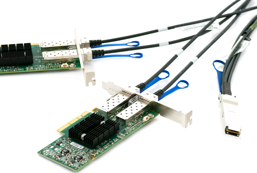 Twinax Cables are mainly used with PCI or PCI-E Card for the short distance interconnection in the server room.
SNS Page


SOPTO Products
- Fiber Optic Transceiver Module
- High Speed Cable
- Fiber Optical Cable
- Fiber Optical Patch Cords
- Splitter CWDM DWDM
- PON Solution
- FTTH Box ODF Closure
- PCI-E Network Card
- Network Cables
- Fiber Optical Adapter
- Fiber Optical Attenuator
- Fiber Media Converter
- PDH Multiplexers
- Protocol Converter
- Digital Video Multiplexer
- Fiber Optical Tools
- Compatible
Related Products
Performance Feature
Stable Transmission Speed
Reliable Transmission
Various Length Selection
Wider Operating Temperature
Good for HPC
Good for Data Center
Twinax Cable Knowledge
Recommended
High Speed Cable Electrical Properties
The electrical properties of the high speed cable (Twinax Cable) mainly includes the Impedance, Attenuation, Intra-pair Skew, Inter-pair Skew, Delay and the attenuation of Differential to Common Mode (SCD21).
What is Impedance?
In electrical engineering, impedance is a measure of the extent to which a circuit opposes the flow of electricity. All materials have some degree of electrical resistance, which causes some energy to be lost as heat, and reduces the flow of current. In the case of direct current (DC), impedance is the same as resistance, and depends solely upon the materials from which the circuit is made. For an alternating current (AC), however, two additional factors can contribute to the impedance: capacitance and inductance. Together these are known as reactance, which is a measure of opposition to a change in current that depends on its frequency, and on the components of the circuit.
Alternating current is constantly changing direction, and does so at a given frequency, which is measured in Hertz (Hz), or cycles per second. Typically, electricity is supplied at 50 or 60 Hz, but this may be changed for specific applications. The frequency can be displayed as a wave on an oscilloscope in terms of current or voltage, with the distance from crest to crest representing a complete cycle. The degree of reactance in a circuit is dependent upon the frequency of the AC supply. More specifically, capacitive reactance decreases with increasing frequency, while inductive reactance increases.
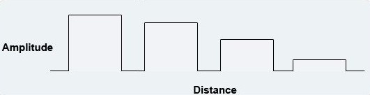
What is Attenuation for high speed cable?
Attenuation is a reduction in signal strength over distance. Attenuation is a common problem of telecommunication cables that causes a decrease in data speeds on longer cables. Attenuation is also known as “loss” and can be countered by data repeaters and amplifiers. While attenuation is a problem for long cables, short cables do not usually experience high amounts of attenuation, even if the same amount of data is transferred.
Signal Attenuation
How Attenuation Works
Attenuation is caused by resistance of electricity in the cable it is transferred through, which causes waste and loss of data. While a computer network is designed to retransmit any information that is lost, the additional data results in a longer transfer time, causing slower data speeds and lower bandwidth among the computers connected to the network. Because of this, cables are limited by a specific amount of attenuation (measured in decibels) over a specified distance before they can be distributed on the open market.
Applications of Attenuation
Attenuation is most often found in cables, but can also be found in wireless and even fiber optic systems due to the propagation of signals over distance. For example, radio waves broadcast from a satellite with spread out over a long distance and will eventually be unreadable if not intercepted.
What is Intra- Pair Skew?
Intra Pair Skew describes the difference of the propagation delay between electrical signals within a signal wire pair. This will be influenced by the mechanical length differences of conductors within a signal pair or by different dielectric constants. This mainly appears in 90° variants of connectors.
What is Inter-Pair Skew?
Inter Pair Skew describes the difference of the propagation delay between two or more signal wire pairs in one cable. The reasons for Inter Pair Skew are comparable with Intra Pair Skew.
Inter Pair Skew leads into a reduction of bandwidth due to the fact that with most of the multi-channel data bus systems all data must be valid simultaneously. Otherwise the time frames for a secure acceptance of valid information must be set unnecessary high.
What is Delay?
Delay describes the transmission time of electrical signal from transmitting end to receiving end. The delay can be test by using TDR mode or TDT mode.
Attenuation of Differential to Common Mode (SCD21)
Attenuation of Differential to Common Mode has a relationship with Intrapair Skew, Insertion Loss and attenuation.
Related Knowledge: