-

- Sopto Home
-

- Special Topic
-
- Twinax Cable Knowledge
-
- High Speed Cable Production Process

Twinax Cable Knowledge
- Cable Labeling as Part of Data Center Management
- How to Correctly Run cables On Servers in a Data Center?
- 4 Realities You Should Consider 10G Ethernet for Your Business
- Is it finally the end of copper?
- Why We Need Both 40G and 100G Ethernet Cable?
- What is Twisted Pair Cable?
- Benefits of Twisted Pair Cable Construction
- Why Copper Is Used in Cables?
- A Brief Look at Ethernet Cable Construction
SOPTO Special Topic
Certificate


Guarantee
Except products belongs to Bargain Shop section, all products are warranted by SOPTO only to purchasers for resale or for use in business or original equipment manufacturer, against defects in workmanship or materials under normal use (consumables, normal tear and wear excluded) for one year after date of purchase from SOPTO, unless otherwise stated...
Return Policies
Defective products will be accepted for exchange, at our discretion, within 14 days from receipt. Buyer might be requested to return the defective products to SOPTO for verification or authorized service location, as SOPTO designated, shipping costs prepaid. .....
Applications
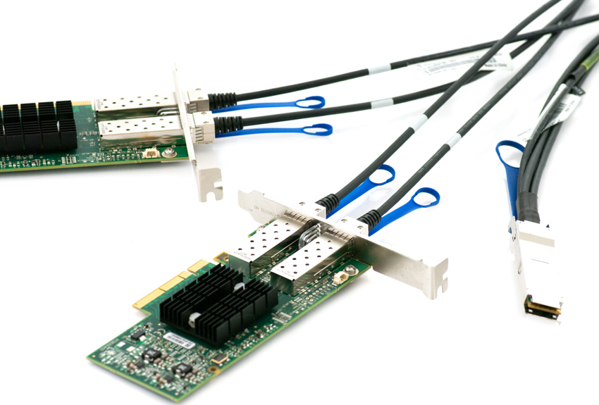 Twinax Cables are mainly used with PCI or PCI-E Card for the short distance interconnection in the server room.
SNS Page


SOPTO Products
- Fiber Optic Transceiver Module
- High Speed Cable
- Fiber Optical Cable
- Fiber Optical Patch Cords
- Splitter CWDM DWDM
- PON Solution
- FTTH Box ODF Closure
- PCI-E Network Card
- Network Cables
- Fiber Optical Adapter
- Fiber Optical Attenuator
- Fiber Media Converter
- PDH Multiplexers
- Protocol Converter
- Digital Video Multiplexer
- Fiber Optical Tools
- Compatible
Related Products
Performance Feature
Stable Transmission Speed
Reliable Transmission
Various Length Selection
Wider Operating Temperature
Good for HPC
Good for Data Center
Twinax Cable Knowledge
Recommended
High Speed Cable Production Process
It is a complex process to manufacture high speed cables because it needs suitable production equipment and mature stable production technology. In the production of high-speed products, the material selection, process parameter and process control as well as specialized laboratory testing of electrical parameters all play a key role. The high speed cable is composed by parallel lines, including 5 production processes, which all affect the performance of the product.
The production process mainly includes:
- Primary Extrusion.
The foundational building block of any good parallel pair construction is primary extrusion. The cables discussed in this article are comprised of primaries that are foam polyolefin materials. Regardless of the extrusion process, either gas injection or chemical foam injection; the process must be continuously improved upon to reach a point of stability that provides for low time delay skew variation.
The measure of stability can be looked at in several ways but in basic terms is simply how precise (small) the cell size is as well as how uniform the structure is distributed amongst the cross section of the dielectric material. The following characteristics / parameters are monitored during the primary extrusion process.
- On Line Continuous Sampling of Primary Extrusion Characteristics such as Capacitance to water, diameter, concentricity, etc. These characteristics are used for various calculations for use in secondary processes.
- Each reel must meet stringent Statistical Requirements – CpK parameters are established for all characteristics for all construction types. Enhanced Data Acquisition Systems are utilized for data collection.
- Taping of the Pair.
The creation of the pair works in harmony with the extrusion process. If the primary wire is not at the required level of foaming consistency then regardless of the capability of taping it will not produce a quality product.
This operation which includes pulling in two primary wires, a drain wire, an aluminum mylar tape, and a heat sealable adhesive mylar tape within one process has a number of critical parameters. This operation is equal in importance to the primary extrusion process. It has an equal number of variables to understand and with the best primary wire, if not in control, can produce poor signal integrity.
The equipment used for this process is internally designed by SOPTO personnel to maintain proprietary information. The following characteristics / parameters are monitored during the taping process.
- The selection of conductors utilized for taping is based on previous operational data, lengths are planned to ensure consistency.
- Tape Tensions, line speeds, conductor and drain tensions, and take-up/capstan tensions are established for all construction types.
Heat seal temperatures and dwell times have been created for each design.
- The tape lay lengths over the pair plays a fundamental role in frequency bandwidth. The short lay lengths are selected to push the attenuation to higher bandwidths. Figure 1 demonstrates the impact of one pair of the construction which has the incorrect tape lay length. This large dip in attenuation has been commonly referred to in the industry as a “suck out”. The dip occurs due to the frequency or repetitiveness of the tape lap which causes geometrical changes within the pair construction.
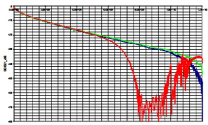
Figure 1: There 100 ohm pairs from a completed cable showing inconsistent attenuation
- For each set, individual pairs are tested for: Impedance, Attenuation and Time Delay Skew at the start of the reel. In-process requirements have been established tighter than finished requirements to identify additional process variation at an earlier stage.
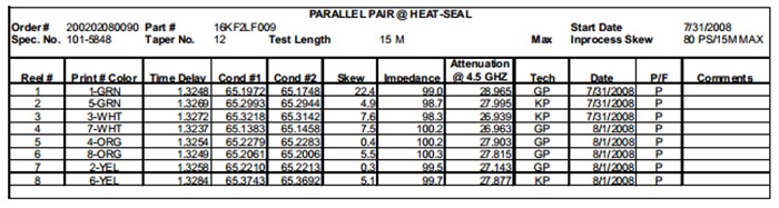
Figure 2: Taping Operation Data
The data shown in figure 2 of the appendix shows typical results obtained at this operation.
- Cabling.
The cabling operation can also be a very critical part of the overall performance of the cable. Depending on the process variation from the combined efforts of both primary and taping it will determine the ease or difficulty in being successful at cabling. The types of cabling used on SOPTO Cable brand products for parallel pair are planetary and bunch cabling methods. The equipment is internally designed by SOPTO personnel to maintain proprietary information.
The traditional SOPTO cable design utilizes an overall polyolefin tape and aluminum mylar tape with the aluminum facing out to make contact with the overall braid. The two tapes and their application are critical in providing excellent signal integrity. The following characteristics / parameters are monitored during the cabling process.
- Cable set-up is critical in ensuring signal integrity. Pair pay-off tension, angle of pair entry, closing dies and lay plate geometry all play critical roles. All must be established for each design / construction and well documented.
- Overall polyolefin tape and aluminum mylar tape tension and application angle must be defined.
- Cabling machine selection / design, because of its inherent structural impact on signal integrity must be carefully chosen and proven for each construction.
- The first piece setup for each manufacturing order is tested to either final or in-process cable requirements for Impedance, Attenuation and Time Delay Skew. All the pairs are analyzed for attenuation consistency.
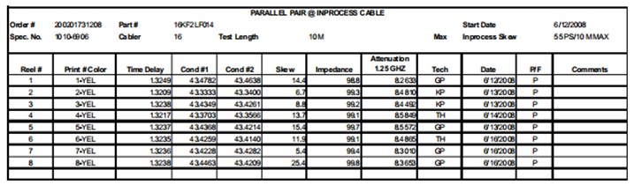
Figure 3 Cabling Operating Date
Figure 3 shows typical data obtained at this operation. Figure 4 and 5 show cable samples measured for attenuation. The first of these plots, figure 6, shows one pair of an eight pair cable that is straying from the other seven. This pair is demonstrating significant attenuation loss which is the result of the compounding effects from all three operations beginning with primaries that have poor foaming consistency resulting in poor time delay skew. Figure 7 shows the typical attenuation curves for an eight pair construction with good consistent attenuation.
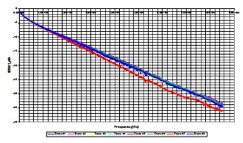
Figure 4: One pair of an eight pair cable with poor attenuation
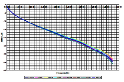
Figure 5: All eight pairs with good attenuation
- Braiding
The braiding operation is not a critical operation for parallel pair product. Normal care for braid bobbin tension, pay-off tension, take-up tension and good general workmanship are sufficient for this operation to maintain signal integrity.
- Jacketing
The jacketing operation is not a critical operation for parallel pair product. Normal care for pay-off tension, take-up tension and good general workmanship are sufficient for this operation to maintain signal integrity. Based on specific customer processes certain jacket applications may be utilized to provide a required effect.
- Laboratory Testing
Laboratory testing is critical in aiding the manufacturing engineering and the design engineering teams. Providing accurate and precise data will enable both teams to make their best educated decisions. There are four fundamental concerns in making accurate bulk cable measurements in the Laboratory.
- Test Equipment – High quality test equipment is critical in making repeatable measurements.
- Sample Preparation – The preparation of bulk copper cable for testing is the second most important concern for repeatable results. This is also related to providing extensive training of the technician but can be enhanced via well documented procedures with good workmanship samples. Characteristics such as sample length, and sample preparation (preciseness in removing the shields, and insulations) becomes extremely important in providing accurate feedback.
- Test Fixtures – The testing of bulk cable provides the engineer/technician with fundamental logistical problems. This is the most difficult issue in testing high speed products. The cable does not have connectors on their ends and therefore some other means of interface must be developed. As discussed previously, after the cable is carefully prepared it must then be soldered to a test fixture. The test fixtures used in our laboratory are of two styles, figures 6 and 7 have been created for this purpose.
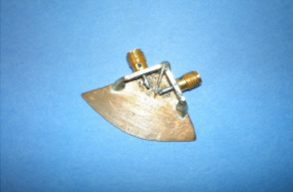
Figure 6 Laboratory Test Fixture for Bandwidths Less than 7GHz
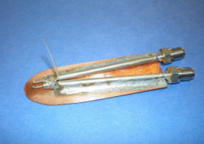
Laboratory Test Fixture for Bandwidths from 7GHz to about 12GHz
Related Knowledge: