-

- Sopto Home
-

- Special Topic
-
- Twinax Cable Knowledge
-
- CX4 AOC Cable Installation Guideline

Twinax Cable Knowledge
- Cable Labeling as Part of Data Center Management
- How to Correctly Run cables On Servers in a Data Center?
- 4 Realities You Should Consider 10G Ethernet for Your Business
- Is it finally the end of copper?
- Why We Need Both 40G and 100G Ethernet Cable?
- What is Twisted Pair Cable?
- Benefits of Twisted Pair Cable Construction
- Why Copper Is Used in Cables?
- A Brief Look at Ethernet Cable Construction
SOPTO Special Topic
Certificate


Guarantee
Except products belongs to Bargain Shop section, all products are warranted by SOPTO only to purchasers for resale or for use in business or original equipment manufacturer, against defects in workmanship or materials under normal use (consumables, normal tear and wear excluded) for one year after date of purchase from SOPTO, unless otherwise stated...
Return Policies
Defective products will be accepted for exchange, at our discretion, within 14 days from receipt. Buyer might be requested to return the defective products to SOPTO for verification or authorized service location, as SOPTO designated, shipping costs prepaid. .....
Applications
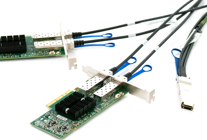 Twinax Cables are mainly used with PCI or PCI-E Card for the short distance interconnection in the server room.
SNS Page


SOPTO Products
- Fiber Optic Transceiver Module
- High Speed Cable
- Fiber Optical Cable
- Fiber Optical Patch Cords
- Splitter CWDM DWDM
- PON Solution
- FTTH Box ODF Closure
- PCI-E Network Card
- Network Cables
- Fiber Optical Adapter
- Fiber Optical Attenuator
- Fiber Media Converter
- PDH Multiplexers
- Protocol Converter
- Digital Video Multiplexer
- Fiber Optical Tools
- Compatible
Related Products
Performance Feature
Stable Transmission Speed
Reliable Transmission
Various Length Selection
Wider Operating Temperature
Good for HPC
Good for Data Center
Twinax Cable Knowledge
Recommended
CX4 AOC Cable Installation Guideline
Active optical cable family is a fully integrated cable designed for direct connection to standard 4-wide I/O electrical high-speed connectors.
Designed for interconnection applications in enterprise data centers and high-performance computer clusters, the optical fiber-based cable delivers significant reach, weight, flexibility and BER advantages compared with electrical-based cabling.
The cables have four differential electrical inputs and outputs, capable of handling a range of high-speed data rates and cable length. The optical cable family targets data rates up to InfiniBand DDR (Dual Data Rate) of 5 Gbps per channel, as well as covering InfiniBand SDR (2.5 Gbps) and XAUI10 GbE applications of 3.125 Gbps per channel.
For system ports installed with media detect, the cable requires no configuration and is a true 'plug-and-play' solution.
Data Rate
The cable has four differential electrical inputs and outputs, each capable of handling data rates up to 5 Gbps per channel, 20 Gbps duplex aggregate. The product is specifically designed to cover XAUI10 GbE applications as well as InfiniBanduse at both single (2.5 G) and double (5 G) Data Rate (SDR and DDR).
Cable Length
The cable is available in standard lengths up to 60 m [196.8 ft], though it is possible extend the cable reach as far as 100 m [328.0 ft]. The handling instructions described below should be considered when choosing the correct length.
How and where the cable will be installed is an important consideration prior to ordering. For example, the length should be chosen to ensure that extreme fiber bends are avoided and that the cable is not pulled taut. In general it is better to choose a slightly longer cable than one that is too short. Due to the light weight and flexibility of the cable storing excess length is straightforward.
Fiber Jacket Type
The cable family is available in two standard optical fiber jacket types.OFNR (Optical Fiber Nonconductive Riser) is a fiber type designed by the National Fire Protection Association (NFPA). The fiber is certified for use in riser applications and engineered to prevent the spread of fire from floor to floor in a building. The Riser compliant cable has a flame propagation of less than 3.6 m [12 ft] and has a temperature of 454 degrees C [850 degrees F] or less at a height of 3.6 m [12 ft] per UL 1666.
OFNP (Optical Fiber Nonconductive Plenum) is a fiber type regulated under the National Fire Protection Association standard NFPA 90A. The fiber is certified for use in plenum applications spaces. The space can facilitate air circulation for heating and air conditioning systems, by providing pathways for either heated / conditioned or return airflows. Plenum compliant cable pass UL 910, Test for Flame-Propagation and
Smoke-Density Values for Electrical and Optical-Fiber Cables Used in Spaces Transporting Environmental Air. In general plenum cables can always replace riser cables, but riser cable cannot replace plenum cable in plenum applications.
The end-user is strongly advised to check with their relevant local authorities on health and safety and fire regulations before choosing the appropriate fiber jacket type for their installation.
INSTALLATION
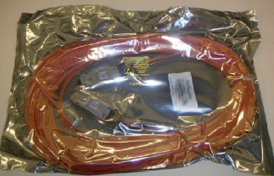
1. Handling of Delivered Parts
The cable is delivered individually sealed in vacuum packed anti-static bags, as shown in Figure 3. The bag is labeled with the part number in both text and bar code format.
2. Fiber Handling
The cable uses a multi-mode optical fiber as the interconnection medium. At installation of the cable into the infrastructure the following additional handling factors should be followed:
- The axial pull force or tensile load on the optical cabling section on the fiber cable should NOT exceed 22 N [4.9 lbf].
- The tensile load (during installation, not related to the force applied to the connector) should not exceed 200 N [45 lbf].
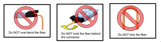
- The minimum allowed Bend Radius of the cable is 25 mm [1 in.], provided that tensile does not exceed 50 N [11.2 lbf].
- The fiber must only be bent in direction perpendicular to the flat side of the fiber ribbon "up" or "down" with connector placed horizontally.
- The connector should NOT be twisted to achieve the correct orientation. The user should reach back approximately 1m [3 ft] on the fiber, and twist the fiber ribbon to allow the connector to rotate to the proper orientation. Failure to do so may result in all the rotational forces acting directly at the fiber terminations.
- Kinking the cable can cause the optical fiber to break.
3. Electrical Installation
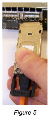
Install the cable as follows:
1. Align the connector as shown in Figure 5.
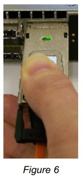
2. Insert the connector into the port receptacle as shown in Figure 6.
3. Ensure the latches (male) on the connector interlock properly with the latch (female) in the CX4 port connector. Refer to Figure 7.
 on the connector interlock properly with the latch (female) in the CX4 port connector.jpg)
After installation, the active cable should function without operator intervention.
4. To remove the connector from the port perform the installation in reverse order. Starting to pull the handle causes the cable to detach. Ensure that the latch is then back in its locked position prior to installation into another port. Refer to Figure 8.
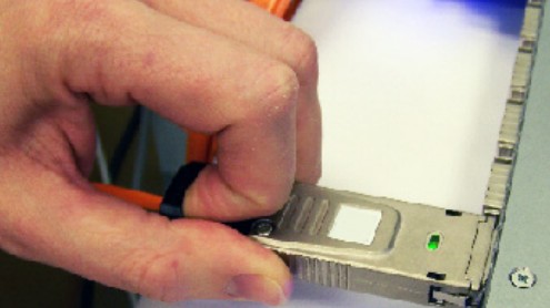
Figure 8
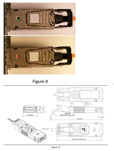
4. Status LED
The CX-4 active optical cable provides status LEDs at each connector end to facilitate installation. Refer to Figure 9 and Figure 10.
On installing the connector into the port the following LED conditions will be observed:
- No Light: indicates no power is being supplied to the connector
- Green Light ONLY: the connector is powered on AND is transmitting traffic on all channels
- Red & Green Light: the connector is powered but a fault has been detected on at least one data channel
- Red Light ONLY: the connector is powered but a hardware fault has been detected in the cable
Related Knowledge: