-

- Sopto Home
-

- Special Topic
-
- Multiplexer Knowledge
-
- How to Use a Mux to Implement a Logic Equation?

Multiplexer Knowledge
- Why is Multiplexing Needed in Data Communication Systems?
- What is Concept of Multiplexing in Telephone System?
- What is Digital TV Frequency?
- Outlook of the WDM Networks
- DWDM Technical Overview
- CWDM Technical Overview
- How to Activate Cable Modems?
- How to Install a Fiber Optic Modem?
- How do I Choose a Best Fiber Modem?
SOPTO Special Topic
Certificate


Guarantee
Except products belongs to Bargain Shop section, all products are warranted by SOPTO only to purchasers for resale or for use in business or original equipment manufacturer, against defects in workmanship or materials under normal use (consumables, normal tear and wear excluded) for one year after date of purchase from SOPTO, unless otherwise stated...
Return Policies
Defective products will be accepted for exchange, at our discretion, within 14 days from receipt. Buyer might be requested to return the defective products to SOPTO for verification or authorized service location, as SOPTO designated, shipping costs prepaid. .....
Applications
Multiplexers can be used to connect PBX, Hot line and other devices of network from central site to user site through fiber optical cable.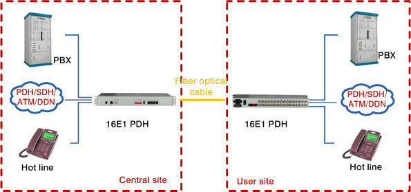
SNS Page


SOPTO Products
- Fiber Optic Transceiver Module
- High Speed Cable
- Fiber Optical Cable
- Fiber Optical Patch Cords
- Splitter CWDM DWDM
- PON Solution
- FTTH Box ODF Closure
- PCI-E Network Card
- Network Cables
- Fiber Optical Adapter
- Fiber Optical Attenuator
- Fiber Media Converter
- PDH Multiplexers
- Protocol Converter
- Digital Video Multiplexer
- Fiber Optical Tools
- Compatible
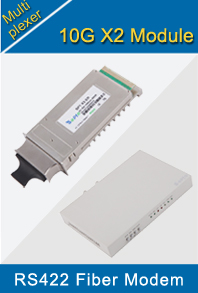
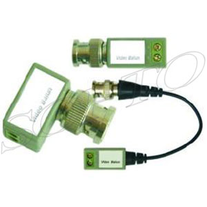
Related Products
Performance Feature
High integration desig
Low power consumption
Good EMC, EMI
Stable and Reliable
Multiplexer Knowledge
Recommended

How to Use a Mux to Implement a Logic Equation?
A logic equation is an alphabetical representation of different combinations of inputs and outputs in a digital circuit. Logic equations adhere to the rules of Boolean Algebra, and each equation has its own "truth table" that designates the "logic state" of each input and output. The two possible logic states are "high" and "low," which correspond to the binary numbers "1" and "0," respectively.
Electrically, these logic states and binary numbers translate into the two digital voltage levels of 5V (high, "1") and 0V (low, "0"). The Multiplexer (MUX) is an electronic component that utilizes those two voltage levels to implement various logic equations in an actual circuit.
Now, let’s build a test circuit follow 7 steps:
- Identify the MUX pins labeled "Vcc" and "Gnd," as listed on the MUX data sheet. Connect Vcc to the five-volt power source and Gnd to circuit ground.
- Identify the "Enable" pin and connect it to circuit ground. The pin may be labeled as "E" with a line over the top of it.
- Connect one end of a 1K resistor to each of the MUX switch pins, which are labeled "S2", "S1" and "S0." Connect the other end of the each resistor to the five-volt source.
- Connect one side of a single-pole switch to each junction of a 1K resistor and a MUX switch pin. Connect the other side of each single-pole switch to circuit ground. Regarding circuit operation, the resistor side is "logic high" and the ground side is "logic low."
- Connect jumper wires to the eight MUX inputs, which are labeled "I0" through "I7." Connect one end of each wire to each input and leave the other end free.
- Connect one leg of a 330 ohm resistor to the output pin of the MUX, which is labeled "Z."
- Connect the anode (longer leg) of an LED to the open leg of the 330 ohm resistor. Connect the cathode (shorter leg) of the LED to circuit ground.
And we should use the MUX Truth Table.
- Locate the truth table on the MUX data sheet.
- Locate the row that has an "H" listed in columns "S2," "S1" and "S0." The row will also list "I7" in the "Z" column. This row signifies the logic equation "ABC=X," which is the equation for a "three-input AND gate."
- Connect the I7 pin of the MUX to the five-volt source.
- Connect all other MUX inputs (I0-I6) to circuit ground.
- Apply power to the circuit and test all eight combinations of the MUX switches, as listed in the MUX truth table. The LED should only light (be a "logic high") when S2, S1 and S0 are all high.
Finally, using a Logic Equation for MUX Configuration
- Find the rows on the MUX truth table where there is an "H" listed in the S0 column. These rows correspond to the logic equation "AB+C=X."
- Connect the MUX inputs, listed in the Z column, to the five-volt source. The correct inputs are I1, I3, I5 and I7.
- Connect the other MUX inputs (I0, I2, I4, I6) to circuit ground.
- Apply power to the circuit and test all eight switch combinations. The LED should light whenever S0 is high.
Tips & Warnings
1. Disregard the truth table row where "Enable" is high.
2. Note which side of each single-pole switch is for logic high and low. Wire all of the single-pole switches in the same direction.
3. In the logic equations, "A" stands for "S2," "B" stands for "S1," "C" stands for "S0" and "X" stands for "Z" (the input listed for Z).
4. In the equation "AB+C=X", the logic state of A and B (S2 and S1) is not important. The combination AB is in a logic "or" with C. Because of the truth table for a logic "or," the logic state of A and B can be either high or low. Therefore, only the logic state of C (S0) is relevant to the state of Z.
5. If the LED becomes hot or turns a different color, immediately disconnect power and check your connections.
6. Take precautions for Electrostatic Discharge when handling Integrated Circuits. Wear an antistatic wrist strap, especially when working with CMOS components.
Sopto supplies high quality multiplexing products, like E+E PDH Multiplexer, Phone Optical Multiplexer and 1-64 Channels Video Multiplexer and so on. For the newest quotes, please contact a Sopto representative by calling 86-755-36946668, or by sending an email to info@sopto.com. For more info, please browse our website.