-

- Sopto Home
-

- Special Topic
-
- Fiber Optics knowledge
-
- Why We Need Fiber Couplers and Splitters?

Fiber Optics knowledge
- Maintained Methods of Fusion Splicer Parts
- How to Use the Fiber Optic Cleaver?
- What are Fixed Attenuators & Variable Attenuators?
- Deployable Fiber Optic Systems for Harsh Mining Environments
- Developing Miniature Fiber Optic Cable Has Become the Trend
- Fiber Optic Cleaning Procedures
- 6 Steps to Selecting a Fiber Optic Cable
- Signal Attenuation Introduction
- How Fiber Transmission Works?
SOPTO Special Topic
Certificate


Guarantee
Except products belongs to Bargain Shop section, all products are warranted by SOPTO only to purchasers for resale or for use in business or original equipment manufacturer, against defects in workmanship or materials under normal use (consumables, normal tear and wear excluded) for one year after date of purchase from SOPTO, unless otherwise stated...
Return Policies
Defective products will be accepted for exchange, at our discretion, within 14 days from receipt. Buyer might be requested to return the defective products to SOPTO for verification or authorized service location, as SOPTO designated, shipping costs prepaid. .....
Applications
Fiber Optis can be used in so many fields:
Data Storage Equipment
Interconnects,Networking
Gigabit Ethernet
FTTx, HDTV,CATV
Aerospace & Avionics
Data Transfer Tests
Network Equipment
Broadcast Automotive
Electronics,Sensing
Oil & Gas, Imaging
Outside Plant,Central Office
Harsh Environment
Data Transmission
Illumination,Institutions
Ship to Shore,Education
Simulation,Military,Space
Unmanned Aerial Vehicles
Semiconductor Equipment
Diagnostics & Troubleshooting
Premise Networks Carrier Networks
Independent Telecommunication Providers
SNS Page


SOPTO Products
- Fiber Optic Transceiver Module
- High Speed Cable
- Fiber Optical Cable
- Fiber Optical Patch Cords
- Splitter CWDM DWDM
- PON Solution
- FTTH Box ODF Closure
- PCI-E Network Card
- Network Cables
- Fiber Optical Adapter
- Fiber Optical Attenuator
- Fiber Media Converter
- PDH Multiplexers
- Protocol Converter
- Digital Video Multiplexer
- Fiber Optical Tools
- Compatible
Related Products
 10G SFP+ Transceiver
 40G QSFP+ Transceiver
Performance Feature
Fiber Optics knowledge
Recommended
Why We Need Fiber Couplers and Splitters?
When using fiber optics, one often needs to use fiber couplers for various purposes. Some examples:
- A coupler can be used as a splitter to couple out some portion of the light circulating in the resonator of fiber laser, for example. Directional 2 × 2 couplers (see Figure 1) are usually used for such purposes.
-

- Figure 1: A 2-by-2 fiber coupler
- The same kind of devices is useful in fiber interferometers, also for combining two inputs. (Note that polarization issues might occur.)
- Dichroic couplers can be used to combine a pump and a signal input for a fiber amplifier, or to remove residual pump light after the amplifier.
- For high-power fiber lasers and amplifiers, one often needs pump couplers with multiple inputs, combining the outputs of several high-power diode bars.
The probably most often used operation principle of a directional fiber coupler is evanescent wave coupling in a configuration where two fiber cores come close to each other. Such a device can be made by heating two bare fibers such that the glass begins to melt and the fibers fuse together. One might also slightly pull the fibers during that process. A refractive index profile obtained in that way is shown in Figure 2:
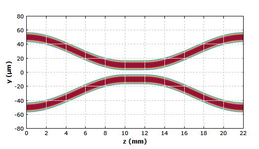
Figure 2: Refractive index profile of a fiber coupler
Both waveguides are single-mode waveguides with a super-Gaussian index profile. The coupling region in the middle is only a few millimeters long. Outside that region, the coupling is negligible, as the mode fields really don't touch each other.
With numerical beam propagation, one can now check what happens when light is injected only into the upper left input port:
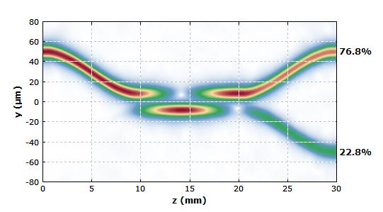
Figure 3: Amplitude distribution in a fiber coupler, obtained with a numerical simulation of beam propagation, done with the software Fiber Power.
In this particular situation, the light first couples almost entirely to the lower waveguide after a short distance, but then back to the upper waveguide, and finally most of the power remains there. As the coupling strength depends sensitively on the wavelength, for some other wavelengths one may e.g. get nearly all power to cross over to the lower output port. The simulated wavelength dependence is shown in Figure 4. The somewhat strange shape of the curve in the longer-wavelength region results from bend losses of the waveguides, which get substantial in that region.
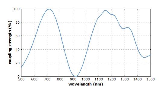
Figure 4: Degree of power coupling as a function of the wavelength.
If the coupling is made weak (through the waveguide distance) but can occur over a longer length, the wavelength sensitivity gets stronger. Conversely, broadband couplers require a strong coupling over a short length.
Note that such couplers are directional couplers: essentially no light couples into the “backward” direction.
Pump couplers for high-power fiber lasers and amplifiers are different in some respects. The input and output fibers are strongly multimode, with large cores and high numerical aperture. The coupling principles can also be different from that in the example case above. For example, instead of evanescent wave coupling one may simply inject light from smaller cores into a large core for the output. Power losses must be carefully minimized – partly because lost light at high power levels might destroy the coupler.
For more information, please browse our website or contact a Sopto representative by calling 86-755-36946668, or by sending an email to info@sopto.com.