-

- Sopto Home
-

- Special Topic
-
- Fiber Optics knowledge
-
- Passive Fiber Optics Mode Info
Fiber Optics knowledge
- Maintained Methods of Fusion Splicer Parts
- How to Use the Fiber Optic Cleaver?
- What are Fixed Attenuators & Variable Attenuators?
- Deployable Fiber Optic Systems for Harsh Mining Environments
- Developing Miniature Fiber Optic Cable Has Become the Trend
- Fiber Optic Cleaning Procedures
- 6 Steps to Selecting a Fiber Optic Cable
- Signal Attenuation Introduction
- How Fiber Transmission Works?
SOPTO Special Topic
Certificate


Guarantee
Except products belongs to Bargain Shop section, all products are warranted by SOPTO only to purchasers for resale or for use in business or original equipment manufacturer, against defects in workmanship or materials under normal use (consumables, normal tear and wear excluded) for one year after date of purchase from SOPTO, unless otherwise stated...
Return Policies
Defective products will be accepted for exchange, at our discretion, within 14 days from receipt. Buyer might be requested to return the defective products to SOPTO for verification or authorized service location, as SOPTO designated, shipping costs prepaid. .....
Applications
Fiber Optis can be used in so many fields:
Data Storage Equipment
Interconnects,Networking
Gigabit Ethernet
FTTx, HDTV,CATV
Aerospace & Avionics
Data Transfer Tests
Network Equipment
Broadcast Automotive
Electronics,Sensing
Oil & Gas, Imaging
Outside Plant,Central Office
Harsh Environment
Data Transmission
Illumination,Institutions
Ship to Shore,Education
Simulation,Military,Space
Unmanned Aerial Vehicles
Semiconductor Equipment
Diagnostics & Troubleshooting
Premise Networks Carrier Networks
Independent Telecommunication Providers
SNS Page


SOPTO Products
- Fiber Optic Transceiver Module
- High Speed Cable
- Fiber Optical Cable
- Fiber Optical Patch Cords
- Splitter CWDM DWDM
- PON Solution
- FTTH Box ODF Closure
- PCI-E Network Card
- Network Cables
- Fiber Optical Adapter
- Fiber Optical Attenuator
- Fiber Media Converter
- PDH Multiplexers
- Protocol Converter
- Digital Video Multiplexer
- Fiber Optical Tools
- Compatible
Related Products
 10G SFP+ Transceiver
 40G QSFP+ Transceiver
Performance Feature
Fiber Optics knowledge
Recommended
Passive Fiber Optics Mode Info
In general, the intensity profile of light propagating in a fiber changes during propagation. It often even evolves in a rather complicated way. As an example, see what happens if we inject a Gaussian beam, which is tilted by 20° against the beam axis, into a fiber with 20 μm core radius and an NA of 0.3:
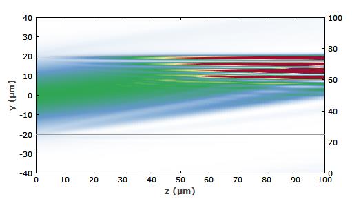
Figure 1: Evolution of the intensity in a multimode fiber. A Gaussian beam with an angle of 20° against the beam axis is injected into the fiber.
(Note that here we show only intensity profiles, as the larger spatial region shown makes it difficult to show wavefronts.)
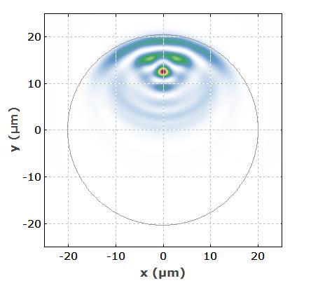
Figure 2: Beam profile in the fiber after propagation over 100 μm.
We have seen the intensity profiles generally evolve in complicated ways. However, there are certain amplitude distributions where the intensity profile remains unchanged during propagation (assuming a lossless fiber). Such field distributions are called modes of the fiber. The simplest of these, the fundamental mode, also called LP01 mode, looks as follows for the fiber in the current example:
For purchasing more fiber optics’ information, please contact a Sopto representative by calling 86-755-36946668, or by sending an email to info@sopto.com.
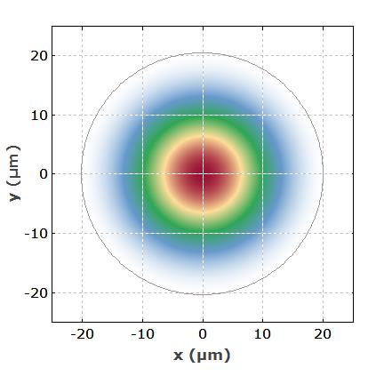
Figure 3: Intensity profile of the fundamental mode in a multimode fiber. The gray circle indicates the core/cladding boundary.
Here is a higher-order mode, the LP37 mode: