-

- Sopto Home
-

- Special Topic
-
- Fiber Optics knowledge
-
- Guiding Light in a Glass Fiber
Fiber Optics knowledge
- Maintained Methods of Fusion Splicer Parts
- How to Use the Fiber Optic Cleaver?
- What are Fixed Attenuators & Variable Attenuators?
- Deployable Fiber Optic Systems for Harsh Mining Environments
- Developing Miniature Fiber Optic Cable Has Become the Trend
- Fiber Optic Cleaning Procedures
- 6 Steps to Selecting a Fiber Optic Cable
- Signal Attenuation Introduction
- How Fiber Transmission Works?
SOPTO Special Topic
Certificate


Guarantee
Except products belongs to Bargain Shop section, all products are warranted by SOPTO only to purchasers for resale or for use in business or original equipment manufacturer, against defects in workmanship or materials under normal use (consumables, normal tear and wear excluded) for one year after date of purchase from SOPTO, unless otherwise stated...
Return Policies
Defective products will be accepted for exchange, at our discretion, within 14 days from receipt. Buyer might be requested to return the defective products to SOPTO for verification or authorized service location, as SOPTO designated, shipping costs prepaid. .....
Applications
Fiber Optis can be used in so many fields:
Data Storage Equipment
Interconnects,Networking
Gigabit Ethernet
FTTx, HDTV,CATV
Aerospace & Avionics
Data Transfer Tests
Network Equipment
Broadcast Automotive
Electronics,Sensing
Oil & Gas, Imaging
Outside Plant,Central Office
Harsh Environment
Data Transmission
Illumination,Institutions
Ship to Shore,Education
Simulation,Military,Space
Unmanned Aerial Vehicles
Semiconductor Equipment
Diagnostics & Troubleshooting
Premise Networks Carrier Networks
Independent Telecommunication Providers
SNS Page


SOPTO Products
- Fiber Optic Transceiver Module
- High Speed Cable
- Fiber Optical Cable
- Fiber Optical Patch Cords
- Splitter CWDM DWDM
- PON Solution
- FTTH Box ODF Closure
- PCI-E Network Card
- Network Cables
- Fiber Optical Adapter
- Fiber Optical Attenuator
- Fiber Media Converter
- PDH Multiplexers
- Protocol Converter
- Digital Video Multiplexer
- Fiber Optical Tools
- Compatible
Related Products
 10G SFP+ Transceiver
 40G QSFP+ Transceiver
Performance Feature
Fiber Optics knowledge
Recommended
Guiding Light in a Glass Fiber
The basic function of any optical fiber is to guide light, i.e., to act as a dielectric waveguide: light injected into one end should stay guided in the fiber. In other words, it must be prevented from getting lost e.g. by reaching the outer surface and escaping there. We explain this here for glass fibers, but the operation principle of plastic optical fibers is the same.
In principle, the simplest solution for guiding light would be a homogeneous glass rod. (If it is thin enough, it can also be bent to some degree.) The outer surface can reflect light via total internal reflection. Due to the large refractive index contrast, this works for a considerable range of input beam angles, and in principle there don't need to be any power losses.
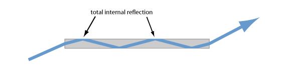
Figure 1: Total internal reflection can be used to guide light in a homogeneous fiber. Note that only partial reflection occurs at the end faces, where the angle of incidence is smaller.
However, this simple solution has some crucial disadvantages:
Due to the high index contrast, even tiny scratches of the glass on the outer surface could lead to substantial optical losses by scattering. Therefore, the outer surface would have to be made with high optical quality and well protected against damage and dirt. This problem can be mitigated only to some extent with some suitable buffer coating around the fiber; such coatings, not being highly homogeneous, can hardly provide very low optical losses.
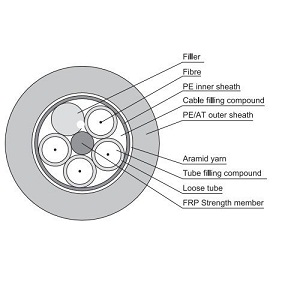
All Dielectric Self-supporting Aerial Cable
Even if the fiber were pretty thin (e.g., with a diameter of 0.1 mm), it would support a huge number of modes, which is bad e.g. when preserving a high beam quality is important.
One can, however, modify the idea of a very clean coating: use another glass region, having a slightly smaller refractive index than the core glass, as a cladding:
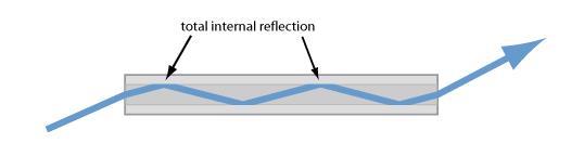
Figure 2: A multimode glass fiber with a cladding, made of glass with a slightly lower refractive index. Total internal reflection can occur at the glass/glass interface, but the incidence angles need to be larger.
That gives us several advantages:
Glass can be much more clean and homogeneous than a plastic buffer coating. That already reduces the losses.
Due to the reduced index contrast at the reflection points, small irregularities of the interface do not cause as serious optical losses as for a glass/air interface. Irregularities at the outer interface do not matter any more, as the light cannot “see” them.
The guiding region – called the fiber core – can now be made much smaller than the total fiber, if this is wanted. One can adapt the core size e.g. to the size of some small light emitter.
With a combination of small core size and weak index contrast one can even obtain single-mode guidance.
Note, however, that smaller index contrasts imply a smaller acceptance angle: total internal reflection can only occur if the incidence angle is above the critical angle. The maximum angle of incidence at the input face of the fiber is then determined by the numerical aperture (NA):
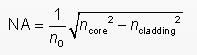
Numerical Aperture
The NA is the Sine of the maximum angle of incidence at the input face. In the equation, n0 is the refractive index of the medium around the fiber, which is close to 1 in case of air.
Particularly in the domain of small cores and weak index contrasts, the simple ray picture does no more represent an accurate model for light propagation, as it ignores the wave nature of light. So let us now consider the wave nature.
First, we imagine at a Gaussian beam in a homogeneous medium (e.g., some glass). Even if such a beam has flat wavefronts initially, within one Rayleigh length it will start diverging significantly:
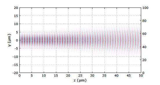
Figure 3: A Gaussian beam with 1.5 μm vacuum wavelength in a homogeneous glass. It initially propagates in a nearly parallel fashion, but eventually diverges.
The divergence is intimately related to a curvature of the wavefronts. Apparently, the wavefronts on the beam axis progress faster in z direction than those at higher or lower positions. That observation can trigger an idea: couldn't we work against that bending of wavefronts by somewhat slowing down the light near the beam axis? That could be done by using an inhomogeneous structure, with a somewhat increased refractive index in the central region. Indeed, this works quite well if we simply increase the core index by 0.014 within a radius of 3μm:
For purchasing more fiber optics’ information, please contact a Sopto representative by calling 86-755-36946668, or by sending an email to info@sopto.com.