-

- Sopto Home
-

- Special Topic
-
- Fiber Optics knowledge
-
- Basic Facts on Fiber Optics Modes
Fiber Optics knowledge
- Maintained Methods of Fusion Splicer Parts
- How to Use the Fiber Optic Cleaver?
- What are Fixed Attenuators & Variable Attenuators?
- Deployable Fiber Optic Systems for Harsh Mining Environments
- Developing Miniature Fiber Optic Cable Has Become the Trend
- Fiber Optic Cleaning Procedures
- 6 Steps to Selecting a Fiber Optic Cable
- Signal Attenuation Introduction
- How Fiber Transmission Works?
SOPTO Special Topic
Certificate


Guarantee
Except products belongs to Bargain Shop section, all products are warranted by SOPTO only to purchasers for resale or for use in business or original equipment manufacturer, against defects in workmanship or materials under normal use (consumables, normal tear and wear excluded) for one year after date of purchase from SOPTO, unless otherwise stated...
Return Policies
Defective products will be accepted for exchange, at our discretion, within 14 days from receipt. Buyer might be requested to return the defective products to SOPTO for verification or authorized service location, as SOPTO designated, shipping costs prepaid. .....
Applications
Fiber Optis can be used in so many fields:
Data Storage Equipment
Interconnects,Networking
Gigabit Ethernet
FTTx, HDTV,CATV
Aerospace & Avionics
Data Transfer Tests
Network Equipment
Broadcast Automotive
Electronics,Sensing
Oil & Gas, Imaging
Outside Plant,Central Office
Harsh Environment
Data Transmission
Illumination,Institutions
Ship to Shore,Education
Simulation,Military,Space
Unmanned Aerial Vehicles
Semiconductor Equipment
Diagnostics & Troubleshooting
Premise Networks Carrier Networks
Independent Telecommunication Providers
SNS Page


SOPTO Products
- Fiber Optic Transceiver Module
- High Speed Cable
- Fiber Optical Cable
- Fiber Optical Patch Cords
- Splitter CWDM DWDM
- PON Solution
- FTTH Box ODF Closure
- PCI-E Network Card
- Network Cables
- Fiber Optical Adapter
- Fiber Optical Attenuator
- Fiber Media Converter
- PDH Multiplexers
- Protocol Converter
- Digital Video Multiplexer
- Fiber Optical Tools
- Compatible
Related Products
 10G SFP+ Transceiver
 40G QSFP+ Transceiver
Performance Feature
Fiber Optics knowledge
Recommended
Basic Facts on Fiber Optics Modes
We now look at various interesting properties of the modes:
- As the previous page mentioned, the intensity profile of a mode stays constant during propagation in the fiber (see Figure 1), at least if it is lossless. The complex amplitude profile does change, but only in a simple way: the complex phase progresses in propagation to the propagation length: φ = β z with the phase constant β. Note that this phase change applies equally to all transverse positions of the profile. Every mode has its own β value, although mode degeneracies (same β values for different modes) can occur.
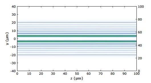
Figure 1: Evolution of beam profile for the LP37 mode. The intensity profile stays constant.
- For a lossless fiber, the phase fronts of modes are always plane. The Poynting vector, showing the direction of energy flow, is always parallel to the fiber axis throughout the mode profile.
- If there are propagation losses, e.g. due to a dopant in the fiber core, the modes are somewhat changed. The wavefronts may now get curved, indicating an energy flow in the radial direction. (For example, if we have absorption only in the core, energy must flow from the cladding to the core. In most cases, though, there are only marginal deformations of wavefronts.) The optical power then decreases exponentially along the propagation direction; the propagation constant obtains a real part, which is minus the amplitude absorption coefficient.
- Generally, the number of guided modes increases as the wavelength gets shorter. For long wavelengths, one may have a single guided mode only (→ single-mode fibers), or in fact even no guided mode at all. (A step-index profile always has at least the fundamental mode, but for some other profiles this is not the case.)
- The modes form a basis (in the mathematical sense), i.e., a complete orthogonal system, for any guided light. In other words, any complex amplitude distribution which is guided by the fiber can be expressed as a linear superposition of the modes. This mode decomposition can be done for monochromatic light as well as for polychromatic light; in the latter case, one just does the decomposition for each frequency component separately.
Note that a superposition of different modes is generally not a mode itself. Generally, different modes have different β values. Therefore, their phase evolution is different, and the overall intensity profile changes during propagation due to the changing interference conditions. If we have only two modes excited, we get a simple mode beating, where the shape of the intensity profile varies periodically; the period is inversely proportional to the difference in β values. If many modes with different β values are excited, the evolution gets very complicated.
For purchasing more fiber optics’ information, please contact a Sopto representative by calling 86-755-36946668, or by sending an email to info@sopto.com.