-

- Sopto Home
-

- Special Topic
-
- PCI-E Card Knowledge
-
- Primary PCIe Applications
PCI-E Card Knowledge
- Info about Network Interface Card Teaming
- How to Setup a Server with Multiple Network Interface Adapters?
- How to Reconnect an Internet Network Adapter for an Acer Aspire?
- 9 Things to Do When Your Internal Network Card Stops Working
- Ethernet Standards NIC for Home Networking
- What Is a Network Interface Adapter?
- How to Configure a Network Interface Card in Linux?
- How should Configure Your NIC for ISA and TMG?
- Recommended Network Card Configuration for Forefront UAG Servers
SOPTO Special Topic
Certificate


Guarantee
Except products belongs to Bargain Shop section, all products are warranted by SOPTO only to purchasers for resale or for use in business or original equipment manufacturer, against defects in workmanship or materials under normal use (consumables, normal tear and wear excluded) for one year after date of purchase from SOPTO, unless otherwise stated...
Return Policies
Defective products will be accepted for exchange, at our discretion, within 14 days from receipt. Buyer might be requested to return the defective products to SOPTO for verification or authorized service location, as SOPTO designated, shipping costs prepaid. .....
Applications
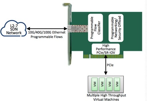
PCI-E NIC Cards provide redundant connectivity to ensure an uninterrupted network connection.
PCI-E NIC Cards are ideal for VM environments with multiple operating systems, requiring shared or dedicated NICs.
They are specially designed for desktop PC clients, servers, and workstations with few PCI Express slots available.
SNS Page


SOPTO Products
- Fiber Optic Transceiver Module
- High Speed Cable
- Fiber Optical Cable
- Fiber Optical Patch Cords
- Splitter CWDM DWDM
- PON Solution
- FTTH Box ODF Closure
- PCI-E Network Card
- Network Cables
- Fiber Optical Adapter
- Fiber Optical Attenuator
- Fiber Media Converter
- PDH Multiplexers
- Protocol Converter
- Digital Video Multiplexer
- Fiber Optical Tools
- Compatible
Related Products
Performance Feature
PCI-E Card Knowledge
Recommended
Primary PCIe Applications
The adoption of the original PCI protocol in PCs and servers paved the way to the widespread availability of components with PCI interfaces for communications systems. While early device development focused on typical PC components such as Ethernet network interface card (NIC) chips, PCMCIA card controllers, and disk controllers, the bus eventually became the protocol of choice for CPU ports on almost all communications devices including framers and NPUs. Given the performance, low cost, and supporting ecosystem the PCI interface offers, this trend will likely continue with PCIe.
Moreover, PCIe offers an additional compelling advantage—low pin count. While a CPU port required 47 signal pins to implement PCI 33/32, it needs only four pins to support an x1 PCIe port. Even though the new interface uses higher speed signals, its reduced pin count and its impact on board layout, routing, and connector design will prove highly attractive to board designers.
.jpg)
Control plane accesses to devices usually involve access to registers or the movement of blocks of data into and out of memory. This function is well suited to the memory-based paradigm used in PCIe. In addition, designers of control plane functions within a card tend to use a hierarchical model where a single housekeeper CPU manages each individual device on the card. This approach is also well matched to the PCIe model. Finally, traffic patterns in a control plane on a single card are almost exclusively between the housekeeper CPU and each individual device, rather than peer to peer between devices.
While PCIe allows multiple priorities of traffic, control plane traffic within a single card is usually low enough in bandwidth to avoid the need to segregate different types of traffic from one another. Over time, designers will migrate from current CPU port protocols on communications cards.
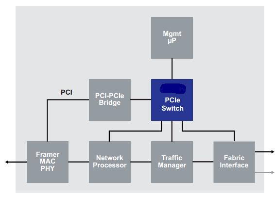
Figure 1 PCIe for on-card control plane connectivity
In many communications systems, devices on one module are controlled by a CPU on another module. Two examples are illustrated below: The line interface module model (see figure 2) and the central processing architecture model.
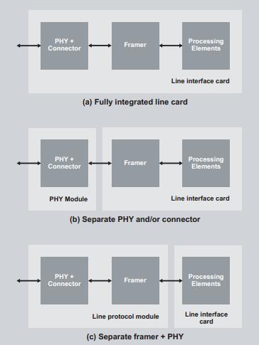
Figure 2 Line card partitioning options
One of the most common customizations in any communications system is selection of I/O. For this reason, line interfaces are often packaged on their own modules. Depending on the system type, this configuration may be limited to the physical aspects of the I/O or allow selection of a number of different protocols. In the first case, users often wish to select or change features like the physical connector type, optical frequency, or output power. In some systems, packaging decisions may dictate separating the line driver/receiver and connectors into a removable module (see option b in figure 2). Other architects may choose to partition their system in a similar way to simplify maintenance, since the line driver often exhibits the highest failure rate.
Some designers will decide to include a framer function with those components on a single removable module (see option c in figure 2). This strategy allows the customer to select not just the reach and frequency of the interface, but also the protocol supported (e.g., ATM over SONET vs. packet over SONET). Again, the architect may partition the system in this manner to simplify component replacement and manage module failure rate estimates.
Conceptually, both of these approaches are an extension of the on-card control plane model that PCIe supports so well. The long reach and low pin count of the interconnection make this approach even more attractive. It should be noted that this paradigm also applies to cards that hold relatively intelligent data plane elements such as I/O processors, digital media adapters (DMAs), NPUs, and ASICs. The test is how much general-purpose processing capability such an element provides on the module. In many of these types of systems, the designer will use a PCI Express switch on the local module to fan out the PCIe connection to as many devices as the system requires.
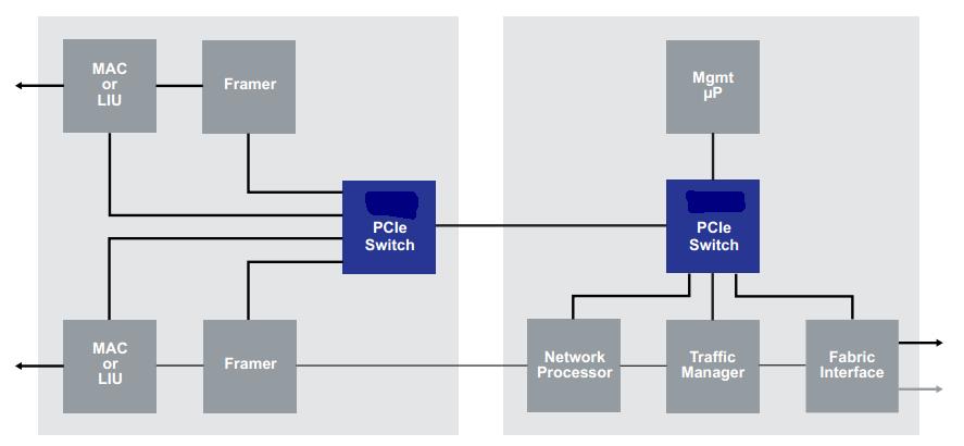
Figure 3. PCIe control plane in modular line interface card
In devices such as access and aggregation nodes, designers can manipulate data moving through the system with a single or a small number of data processing elements. This approach allows the designer to use a highly centralized architecture and to keep individual line interface cards very simple (see figure 6). Typically, these systems use a centralized control processor, since lower data manipulation complexity usually reduces the complexity of the control system.
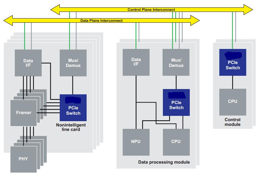
Figure 4. Central Processing Architecture
For more information, please browse our website or contact a Sopto representative by calling 86-755-36946668, or by sending an email to info@sopto.com.