-

- Sopto Home
-

- Special Topic
-
- Multiplexer Knowledge
-
- Gates and Decoders and Multiplexers Introduction

Multiplexer Knowledge
- Why is Multiplexing Needed in Data Communication Systems?
- What is Concept of Multiplexing in Telephone System?
- What is Digital TV Frequency?
- Outlook of the WDM Networks
- DWDM Technical Overview
- CWDM Technical Overview
- How to Activate Cable Modems?
- How to Install a Fiber Optic Modem?
- How do I Choose a Best Fiber Modem?
SOPTO Special Topic
Certificate


Guarantee
Except products belongs to Bargain Shop section, all products are warranted by SOPTO only to purchasers for resale or for use in business or original equipment manufacturer, against defects in workmanship or materials under normal use (consumables, normal tear and wear excluded) for one year after date of purchase from SOPTO, unless otherwise stated...
Return Policies
Defective products will be accepted for exchange, at our discretion, within 14 days from receipt. Buyer might be requested to return the defective products to SOPTO for verification or authorized service location, as SOPTO designated, shipping costs prepaid. .....
Applications
Multiplexers can be used to connect PBX, Hot line and other devices of network from central site to user site through fiber optical cable.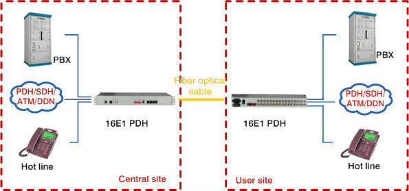
SNS Page


SOPTO Products
- Fiber Optic Transceiver Module
- High Speed Cable
- Fiber Optical Cable
- Fiber Optical Patch Cords
- Splitter CWDM DWDM
- PON Solution
- FTTH Box ODF Closure
- PCI-E Network Card
- Network Cables
- Fiber Optical Adapter
- Fiber Optical Attenuator
- Fiber Media Converter
- PDH Multiplexers
- Protocol Converter
- Digital Video Multiplexer
- Fiber Optical Tools
- Compatible
Related Products
Performance Feature
High integration desig
Low power consumption
Good EMC, EMI
Stable and Reliable
Multiplexer Knowledge
Recommended
Gates and Decoders and Multiplexers Introduction
Gates
Logic gates (or simply gates) are the fundamental building blocks of digital circuitry. As their name implies, they function by “opening” or “closing” to admit or reject the flow of digital information. Gates implement electronically simple logical operations on boolean (Bool’s algebra) variables, i.e. variables that can have only one of two states (0/1, low/high, false/true).
From an electrical point of view and for the TTL (transistor-transistor-logic) family of digital electronics, any voltage in the range 0-0,7 V and in the range 2,5-5 V, represent logic states 0 and 1, respectively. In the following figure the accepted electronic symbols for different gates are shown, along with their corresponding “truth tables” and their symbolic logical expressions. All variables (X, A, B, …) are booleans.
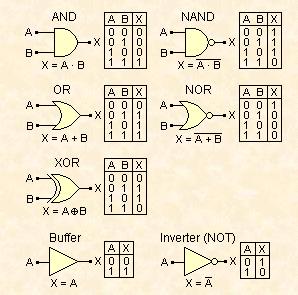
Accepted electronic symbols for different gates
The most typical logical operations are implemented by AND and OR gates. The logical expression for the AND operation is “if A is true AND B is true then X is true”, and for the OR operation is “if A is true OR B is true then X is true”. The inverted logic AND and OR gates are commonly known as NAND (Not AND) and NOR (Not OR) gates. A XOR (Exclusive-OR) gate implements the logical expression “if A is different than B then X is true”, hence sometimes this gate is called “inequality comparator”.
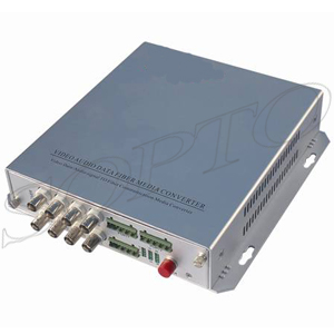
Video + Audio + Data Multiplexer
The buffer and the inverter are not gates but their use is closely associated with them. A buffer doesn’t change the logic state of its input. It is only occasionally used for increasing the fan-out, i.e. the capability of the output of one gate to drive a number of other gates. The inverter is much more important and it is used for inverting a logic state, i.e. for performing the logical operation of negation (NOT).
The logical expressions for a buffer and an inverter are “X is A” and “X is NOT A”, respectively. AND, OR, NAND and NOR gates can have more than 2 inputs. In this case their truth tables are extended to all inputs combinations and their corresponding expressions as well. For example, the logical expression for a 4-input AND is “if A is true AND B is true AND C is true AND D is true then X is true”. The corresponding expression for a 3-input NOR gate is “if A is true OR B is true OR C is true then X is false”
Decoders
Decoders are circuits with two or more inputs and one or more outputs, resulting by combining various types of gates. Their basic function is to accept a binary word (code) as an input and crea-te a different binary word as an output. A typical decoder is the so-called full adder (3 inputs-2 outputs) implementing the addition of two one-digit numbers (Ai, Bi) taking into consideration the status of any previous carry (Ci-1), resulting into the sum (Si), and generating a new carry (Ci). The addition of two 1-digits numbers and the correspon¬ding truth table of full adder are shown below:
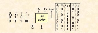
Addition of two 1-digits numbers and the corresponding truth table of full adder
N full adders can be cascaded to form a unit for the addition of two N-digits binary numbers. Decoders with any type of truth table can be constructed by using simple or complicated combinations of gates. Implementation of Bool’s algebra rules generally simplifies the overall design. Simple and useful decoders are the so-called “2-to-4” and “3-to-8” decoders.
Multiplexers
Generally, multiplexers are circuits behaving like a controlled rotary switch, i.e. any one of a number of inputs may be selected as output. In digital electronics, a multiplexer is a combination of logic gates resulting into circuits with two or more inputs (data inputs) and one output. The selection of the channel to be read into the output is controlled by supplying a specific digital word to a different set of inputs (select inputs). A typical 4 input channels (D3-D0) digital multiplexer, and its corresponding truth table is shown below:
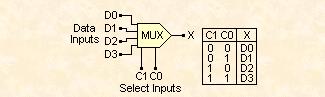
A Typical 4 input channels digital multiplexer truth table
The active input channel is selected by supplying the appropriate code to select inputs (C1, C0).
For more info, please browse our website or contact a Sopto representative by calling 86-755-36946668, or by sending an email to info@sopto.com.