-

- Sopto Home
-

- Special Topic
-
- FTTH Knowledge
-
- Frame Installation and Acceptance Testing

FTTH Knowledge
- Solving the FTTH Rollout Problem in Multiple Dwelling Units
- WDM PON Introduction FAQ
- A Simple Overview of Optical Power Meter
- ODN is based on PON FTTH Optical Cable Network of the Device
- Using an OTDR to be an Expert in Fiber Link Testing
- How FTTH Broadband Works?
- Connections among Fiber Terminal Boxes & Patch Cables & Pigtails
- Easy to Install a Fiber Terminal Box
- What is Arrayed Waveguide Grating?
SOPTO Special Topic
Certificate


Guarantee
Except products belongs to Bargain Shop section, all products are warranted by SOPTO only to purchasers for resale or for use in business or original equipment manufacturer, against defects in workmanship or materials under normal use (consumables, normal tear and wear excluded) for one year after date of purchase from SOPTO, unless otherwise stated...
Return Policies
Defective products will be accepted for exchange, at our discretion, within 14 days from receipt. Buyer might be requested to return the defective products to SOPTO for verification or authorized service location, as SOPTO designated, shipping costs prepaid. .....
Applications

Sopto supply the best FTTH solutions for your network!
SNS Page


SOPTO Products
- Fiber Optic Transceiver Module
- High Speed Cable
- Fiber Optical Cable
- Fiber Optical Patch Cords
- Splitter CWDM DWDM
- PON Solution
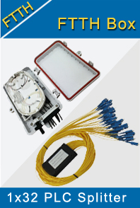
- FTTH Box ODF Closure
- PCI-E Network Card
- Network Cables
- Fiber Optical Adapter
- Fiber Optical Attenuator
- Fiber Media Converter
- PDH Multiplexers
- Protocol Converter
- Digital Video Multiplexer
- Fiber Optical Tools
- Compatible
Related Products
Performance Feature
FTTH Knowledge
Recommended
Frame Installation and Acceptance Testing
After feeder and distribution cable construction is complete, the system is ready for frame installation. The first frame is the fiber distribution hub (FDH), typically housed in an outside cabinet that also contains splitters.
At the FDH, all fibers coming from the CO are connectorized or spliced to the splitters. Splitter outputs are placed in the parking lot, with pigtails stored in a separate path to reduce fiber congestion.
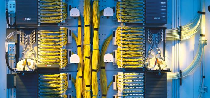
Optical Distribution Frame (ODF)
The second frame, the access or drop terminal, which is located close to the customer premises, consists of a splice enclosure located either on a pole or in a manhole. Several fibers – usually four, six, eight or 12 are extracted from the cable and spliced to be connected to drop cables.
The third frame installed is usually the Optical Distribution Frame (ODF) cabinet of the optical line terminal (OLT), which is located at the CO. As in the other frames, the fiber is spliced to a pig-tail to be connected to the patch panel.
At the end of this process, the feeder and distribution network is complete and ready for end-to-end acceptance testing, including overall distance, insertion loss (IL) and optical return loss (ORL) tests. Before acceptance testing can begin, technicians must ensure that the connectors and patch cords (both those used to test and those used in the network) meet network operator requirements for IL and reflectance.
They may then perform acceptance testing with either an OTDR (1310nm/1550nm) or a source/power meter/ORL meter (1310nm/1550nm) combination. Each operator will have specific requirements for loss, distance and ORL based on the fiber cable network design. If the splitter is connectorized, testers should perform separate feeder and distribution network acceptance tests using test equipment connected at the ODF. They should measure from the ODF to the OLT and from the ODF to the customer premises. If the splitter is spliced, testers should perform end-to-end measurement from the customer premises to the OLT.
In large networks, other ODFs may be located on the feeder to distribute the different cables. The same process should be performed on these frames. Testers should then compare results to the requirements and take corrective action when needed. If the issue involves connections or jumpers, they should test the corrective action with the same loss-test tools. Each result should be recorded in the unit and also on a customer network database for maintenance purposes.
The final acceptance test consists of characterizing the complete optical network. It includes continuity checks, IL and ORL measurements of the end-to-end network through analysis of the transmission optical wavelengths. Testers select a minimum of two wavelengths (usually 1310 nm and 1550 nm) to identify any macro-bends along the network, a common fault in short-distance and high-fiber-count networks.
With a combination source, power meter and ORL meter, the operator can perform automatic continuity checks and measure end-to-end IL as well as end-to-end ORL. ORL testing is particularly important if the operator is using analog video at 1550nm, a technology sensitive to reflectance.
After all the frames have been installed, acceptance testing can begin. Acceptance tests include insertion loss, optical return loss and overall distance tests.
And what should we do after acceptance testing? For more information, please to the “Turn-up tests” and “Turning up Services”