-

- Sopto Home
-

- Special Topic
-
- FTTH Knowledge
-
- Fiber Installation Testing

FTTH Knowledge
- Solving the FTTH Rollout Problem in Multiple Dwelling Units
- WDM PON Introduction FAQ
- A Simple Overview of Optical Power Meter
- ODN is based on PON FTTH Optical Cable Network of the Device
- Using an OTDR to be an Expert in Fiber Link Testing
- How FTTH Broadband Works?
- Connections among Fiber Terminal Boxes & Patch Cables & Pigtails
- Easy to Install a Fiber Terminal Box
- What is Arrayed Waveguide Grating?
SOPTO Special Topic
Certificate


Guarantee
Except products belongs to Bargain Shop section, all products are warranted by SOPTO only to purchasers for resale or for use in business or original equipment manufacturer, against defects in workmanship or materials under normal use (consumables, normal tear and wear excluded) for one year after date of purchase from SOPTO, unless otherwise stated...
Return Policies
Defective products will be accepted for exchange, at our discretion, within 14 days from receipt. Buyer might be requested to return the defective products to SOPTO for verification or authorized service location, as SOPTO designated, shipping costs prepaid. .....
Applications

Sopto supply the best FTTH solutions for your network!
SNS Page


SOPTO Products
- Fiber Optic Transceiver Module
- High Speed Cable
- Fiber Optical Cable
- Fiber Optical Patch Cords
- Splitter CWDM DWDM
- PON Solution
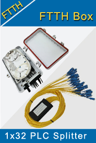
- FTTH Box ODF Closure
- PCI-E Network Card
- Network Cables
- Fiber Optical Adapter
- Fiber Optical Attenuator
- Fiber Media Converter
- PDH Multiplexers
- Protocol Converter
- Digital Video Multiplexer
- Fiber Optical Tools
- Compatible
Related Products
Performance Feature
FTTH Knowledge
Recommended
Fiber Installation Testing
Fiber connectors are widely known as the weakest points in a network. The more connections in a network, the greater is the potential for problems caused by improper handling during installation, operation, expansion and maintenance.
Before mating any connectors, follow this simple inspection process to ensure that fiber end faces are clean.
Step 1: Inspect. Use a probe micro-scope to inspect the fiber. If the fiber is dirty, go to Step2. If the fiber is clean, go ahead and connect.
Step 2: Clean. If the fiber is dirty, use a cleaning tool to clean the fiber end face.
Step 3: Inspect. Use a probe micro-scope to re-inspect and confirm that the fiber is clean. If the fiber is still dirty, go back to Step 2. If the fiber is clean, go ahead and connect.
In a passive optical network (PON) application – the most common FTTH flavor – the optical cable containing the fibers is laid using one of three methods: direct burial installation, duct installation or aerial installation. Feeder cable and the distribution sections then may be spliced in an enclosure, either to join two cables or to divide one large cable into multiple smaller cables to diverge to different locations.
After each splice, perform optical time domain reflectometer (OTDR) measurements from the central office (CO) at 1310 nm and 1550 nm to verify splice quality. Measuring from both sides of the cable is necessary to determine the optical loss of each fusion splice.
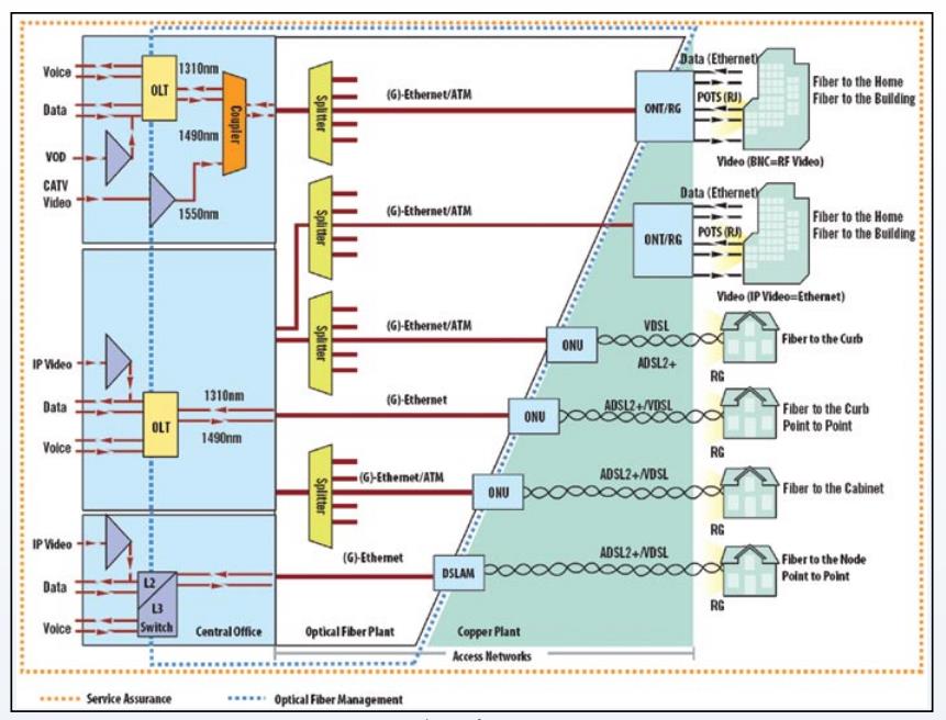
Typical FTTx Infrastructure
Related Knowledge:
FTTH In-house Communication Line process