-

- Sopto Home
-

- Special Topic
-
- Multiplexer Knowledge
-
- Understanding 1 to 4 Demultiplexer

Multiplexer Knowledge
- Why is Multiplexing Needed in Data Communication Systems?
- What is Concept of Multiplexing in Telephone System?
- What is Digital TV Frequency?
- Outlook of the WDM Networks
- DWDM Technical Overview
- CWDM Technical Overview
- How to Activate Cable Modems?
- How to Install a Fiber Optic Modem?
- How do I Choose a Best Fiber Modem?
SOPTO Special Topic
Certificate


Guarantee
Except products belongs to Bargain Shop section, all products are warranted by SOPTO only to purchasers for resale or for use in business or original equipment manufacturer, against defects in workmanship or materials under normal use (consumables, normal tear and wear excluded) for one year after date of purchase from SOPTO, unless otherwise stated...
Return Policies
Defective products will be accepted for exchange, at our discretion, within 14 days from receipt. Buyer might be requested to return the defective products to SOPTO for verification or authorized service location, as SOPTO designated, shipping costs prepaid. .....
Applications
Multiplexers can be used to connect PBX, Hot line and other devices of network from central site to user site through fiber optical cable.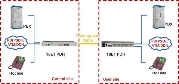
SNS Page


SOPTO Products
- Fiber Optic Transceiver Module
- High Speed Cable
- Fiber Optical Cable
- Fiber Optical Patch Cords
- Splitter CWDM DWDM
- PON Solution
- FTTH Box ODF Closure
- PCI-E Network Card
- Network Cables
- Fiber Optical Adapter
- Fiber Optical Attenuator
- Fiber Media Converter
- PDH Multiplexers
- Protocol Converter
- Digital Video Multiplexer
- Fiber Optical Tools
- Compatible
Related Products
Performance Feature
High integration desig
Low power consumption
Good EMC, EMI
Stable and Reliable
Multiplexer Knowledge
Recommended
Understanding 1 to 4 Demultiplexer
Demultiplexer means one to many. A demultiplexer is a circuit with one input and many output. By applying control signal, we can steer any input to the output. Few types of demultiplexer are 1-to 2, 1-to-4, 1-to-8 and 1-to 16 demultiplexer.
.jpg)
1-64 Channels Video Multiplexer
Following figure illustrate the general idea of a demultiplexer with 1 input signal, m control signals, and n output signals.
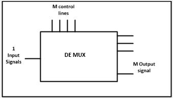
Demultiplexer Pin Diagram
The 1-to-4 demultiplexer has 1 input bit, 2 control bit, and 4 output bits. An example of 1-to-4 demultiplexer is IC 74155. The 1-to-4 demultiplexer is shown in figure below:
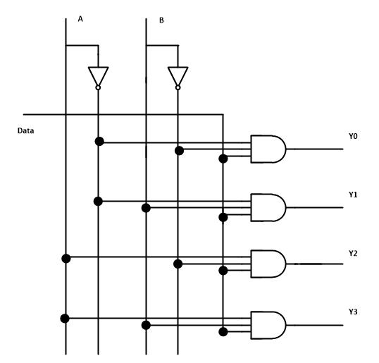
1 to 4 Dempultiplexer Circuit Diagram
The input bit is labeled as Data D. This data bit is transmitted to the data bit of the output lines. This depends on the value of AB, the control input.
When AB = 01, the upper second AND gate is enabled while other AND gates are disabled. Therefore, only data bit D is transmitted to the output, giving Y1 = Data.
If D is low, Y1 is low. IF D is high, Y1 is high. The value of Y1 depends upon the value of D. All other outputs are in low state.
If the control input is changed to AB = 10, all the gates are disabled except the third AND gate from the top. Then, D is transmitted only to the Y2 output, and Y2 = Data.
Example of 1-to-16 demultiplexer is IC 74154 it has 1 input bit, 4 control bits and 16 output bit.
For purchasing more high quality multiplexers with low cost or for more products’ information, please contact a Sopto representative by calling 86-755-36946668, or by sending an email to info@sopto.com.