-

- Sopto Home
-

- Special Topic
-
- Multiplexer Knowledge
-
- The Multiplexing Principles of SDH

Multiplexer Knowledge
- Why is Multiplexing Needed in Data Communication Systems?
- What is Concept of Multiplexing in Telephone System?
- What is Digital TV Frequency?
- Outlook of the WDM Networks
- DWDM Technical Overview
- CWDM Technical Overview
- How to Activate Cable Modems?
- How to Install a Fiber Optic Modem?
- How do I Choose a Best Fiber Modem?
SOPTO Special Topic
Certificate
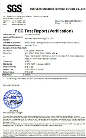
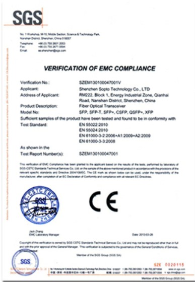
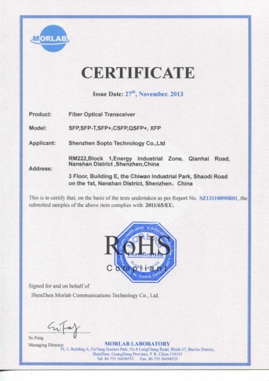
Guarantee
Except products belongs to Bargain Shop section, all products are warranted by SOPTO only to purchasers for resale or for use in business or original equipment manufacturer, against defects in workmanship or materials under normal use (consumables, normal tear and wear excluded) for one year after date of purchase from SOPTO, unless otherwise stated...
Return Policies
Defective products will be accepted for exchange, at our discretion, within 14 days from receipt. Buyer might be requested to return the defective products to SOPTO for verification or authorized service location, as SOPTO designated, shipping costs prepaid. .....
Applications
Multiplexers can be used to connect PBX, Hot line and other devices of network from central site to user site through fiber optical cable.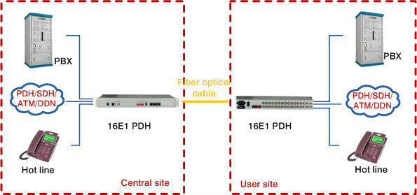
SNS Page


SOPTO Products
- Fiber Optic Transceiver Module
- High Speed Cable
- Fiber Optical Cable
- Fiber Optical Patch Cords
- Splitter CWDM DWDM
- PON Solution
- FTTH Box ODF Closure
- PCI-E Network Card
- Network Cables
- Fiber Optical Adapter
- Fiber Optical Attenuator
- Fiber Media Converter
- PDH Multiplexers
- Protocol Converter
- Digital Video Multiplexer
- Fiber Optical Tools
- Compatible
Related Products
Performance Feature
High integration desig
Low power consumption
Good EMC, EMI
Stable and Reliable
Multiplexer Knowledge
Recommended


The Multiplexing Principles of SDH
-
Mapping - A process used when tributaries are adapted into Virtual Containers (VCs) by adding justification bits and Path Overhead (POH) information.
-
Aligning - This process takes place when a pointer is included in a Tributary Unit (TU) or an Administrative Unit (AU), to allow the first byte of the Virtual Container to be located.
-
Multiplexing - This process is used when multiple lower-order path layer signals are adapted into a higher-order path signal, or when the higher-order path signals are adapted into a Multiplex Section.
-
Stuffing - SDH has the ability to handle various input tributary rates from PDH. As the tributary signals are multiplexed and aligned, some spare capacity has been designed into the SDH frame to provide enough space for all these various tributary rates. Therefore, at certain points in the multiplexing hierarchy, this space capacity is filled with "fixed stuffing" bits that carry no information, but are required to fill up the particular frame.
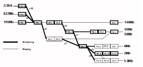
The Figure1 at the below illustrates the ITU-T SDH multiplexing structure. The notations in the boxes, such as C-1, VC-3, and AU-4, are explained in the Figure2.
ITU-T SDH multiplexing structure
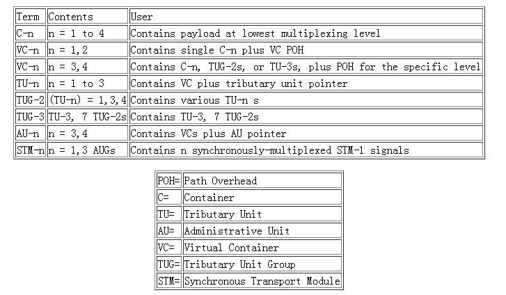
Notations Illustration
At the lowest level, containers (C) are input to virtual containers (VC). The purpose of this function is to create a uniform VC payload by using bit-stuffing to bring all inputs to a common bit-rate ready for synchronous multiplexing. Various containers (ranging from VC-11 at 1.728 Mbit/s to VC-4 at 139.264 Mbit/s) are covered by the SDH hierarchy. Next, VCs are aligned into tributary units (TUs), where pointer processing operations are implemented.
These initial functions allow the payload to be multiplexed into TU groups (TUGs). As the figure illustrates, the xN label indicates the multiplexing integer used to multiplex the TUs to the TUGs. The next step is the multiplexing of the TUGs to higher level VCs, and TUG-2 and TUG-3 are multiplexed into VC-3 (ANSI mappings) and VC-4. These VCs are multiplexed with fixed byte-stuffing to form administration units (AUs) which are finally multiplexed into the AU group (AUG). This payload then is multiplexed into the Synchronous Transport Module (STM).