-

- Sopto Home
-

- Special Topic
-
- Multiplexer Knowledge
-
- Creating Multiplexers Using Logic Gates

Multiplexer Knowledge
- Why is Multiplexing Needed in Data Communication Systems?
- What is Concept of Multiplexing in Telephone System?
- What is Digital TV Frequency?
- Outlook of the WDM Networks
- DWDM Technical Overview
- CWDM Technical Overview
- How to Activate Cable Modems?
- How to Install a Fiber Optic Modem?
- How do I Choose a Best Fiber Modem?
SOPTO Special Topic
Certificate


Guarantee
Except products belongs to Bargain Shop section, all products are warranted by SOPTO only to purchasers for resale or for use in business or original equipment manufacturer, against defects in workmanship or materials under normal use (consumables, normal tear and wear excluded) for one year after date of purchase from SOPTO, unless otherwise stated...
Return Policies
Defective products will be accepted for exchange, at our discretion, within 14 days from receipt. Buyer might be requested to return the defective products to SOPTO for verification or authorized service location, as SOPTO designated, shipping costs prepaid. .....
Applications
Multiplexers can be used to connect PBX, Hot line and other devices of network from central site to user site through fiber optical cable.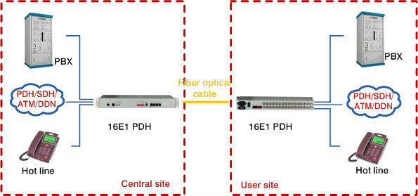
SNS Page


SOPTO Products
- Fiber Optic Transceiver Module
- High Speed Cable
- Fiber Optical Cable
- Fiber Optical Patch Cords
- Splitter CWDM DWDM
- PON Solution
- FTTH Box ODF Closure
- PCI-E Network Card
- Network Cables
- Fiber Optical Adapter
- Fiber Optical Attenuator
- Fiber Media Converter
- PDH Multiplexers
- Protocol Converter
- Digital Video Multiplexer
- Fiber Optical Tools
- Compatible
Related Products
Performance Feature
High integration desig
Low power consumption
Good EMC, EMI
Stable and Reliable
Multiplexer Knowledge
Recommended

Creating Multiplexers Using Logic Gates
So what’s a multiplexer you ask? A multiplexer is an integrated circuit that takes a number of inputs and outputs a smaller number of outputs. In this case we’re aiming at creating a 4-to-1 multiplexer. As the name implies, it takes four inputs and outputs exactly one output, determined by a select input. Depending on the number of input lines, one or more select lines may be required. For 2n input lines, n select lines are needed. In hardware terms, this is basically the simplest of switches.
.jpg)
Creating a 2-to-1 multiplexer
To start out easy, we’ll create a multiplexer taking two inputs and a single selector line. With inputs A and B and select line S, if S is 0, the A input will be the output Z. If S is 1, the B will be the output Z.
The boolean formula for the 2-to-1 multiplexer looks like this:
Z = (A ∧ ¬S) ∨ (B ∧ S)
If you’re not used to boolean algebra, it may be easier to see it represented in SQL:
SELECT @Z = (A & ~S) | (B & S)
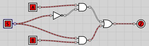
By ANDing A and B with NOT S and S respectively, we’re guaranteed that either A or B will be output. Creating the circuit, it looks like this:
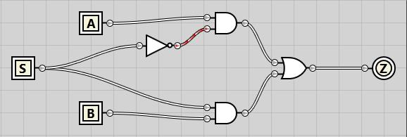
ANDing A and B with NOT S and S respectively
If we enable both A and B inputs but keep S disabled, we see that the A input is passed all the way through to the Z output:
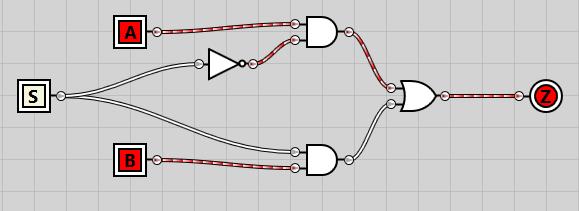
A and B input enable, S disabled
And if we enable the S selector line, B is passed through to Z as the output:
Enable the S selector line
Creating a 4-to-1 multiplexer
Now that we’ve created the simplest of multiplexers, let’s get on with the 4-to-1 multiplexer. Given that we have 22 inputs, we need two selector lines. The logic is just as before – combining the two selector lines, we have four different combinations. Each combination will ensure that one of the input lines A-D are passed through as the output Z. The formula looks like this:
Z = (A ∧ ¬S0 ∧ ¬S1) ∨ (B ∧ S0 ∧ ¬S1) ∨ (C ∧ ¬S0 ∧ S1) ∨ (D ∧ S0 ∧ S1)
And in SQL:
SELECT Z = (A & ~S0 & ~S1) | (B & S0 & ~S1) | (C & ~S0 & S1) | (D & S0 & S1)
The circuit is pretty much the same as in the 2-to-1 multiplexer, except we add all four inputs and implement the 4-input boolean formula, with S0 on top and S1 on bottom:
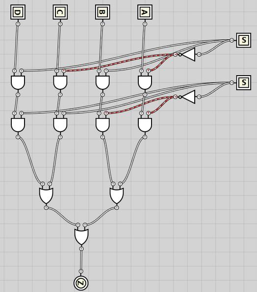
4-to-1 multiplexer Circuit
I’ll spare you a demo of all the states and just show all four inputs activated while the signal value of 0b10 results in C being pass through to Z as the result:
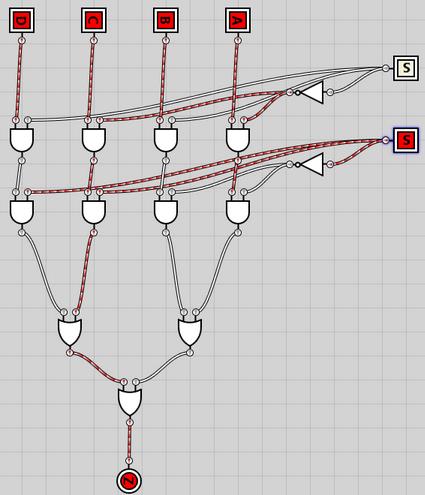
Signal value of 0b10 results in C being pass through to Z
Combining two 4-to-1 multiplexers into an 8-to-1 multiplexer
I’ll spare you the algebraic logic this time as it follows the same pattern as previously, except it’s starting to become quite verbose. In the following circuit I’ve taken the exact 4-to-1 multiplexer circuit that we created just before, and turned it into an integrated circuit (just as I converted the 2-to-1 multiplexer into an integrated circuit). I’ve then added 8 inputs, A through H as well as three selector inputs, S0 through S2.
S0 and S1 are passed directly into each of the 4-1 multiplexers, no matter the value of S2. This means both 4-1 multiplexers are completely unaware of S2s existence. However, as the outputs from each of the 4-1 multiplexers are passed into a 2-1 multiplexer connected to the S2 selector line, S2 determines which of the 4-1 multiplexers get to deliver the output.
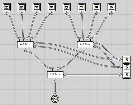
4-1 Mux passed to 2-1 Mux
Here’s an example where S2 defines the output should come from the second (leftmost) 4-1 multiplexer, while the S0 and S1 selector lines defines the input should come from the second input in that multiplexer, meaning input F gets passed through as the result Z.
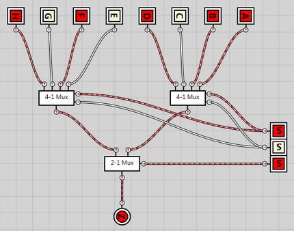
Example- input F gets passed through as the result Z
For more info, please browse our website or contact a Sopto representative by calling 86-755-36946668, or by sending an email to info@sopto.com.