-

- Sopto Home
-

- Special Topic
-
- Multiplexer Knowledge
-
- 4 x 1 Digital Multiplexer Designing Experiment

Multiplexer Knowledge
- Why is Multiplexing Needed in Data Communication Systems?
- What is Concept of Multiplexing in Telephone System?
- What is Digital TV Frequency?
- Outlook of the WDM Networks
- DWDM Technical Overview
- CWDM Technical Overview
- How to Activate Cable Modems?
- How to Install a Fiber Optic Modem?
- How do I Choose a Best Fiber Modem?
SOPTO Special Topic
Certificate


Guarantee
Except products belongs to Bargain Shop section, all products are warranted by SOPTO only to purchasers for resale or for use in business or original equipment manufacturer, against defects in workmanship or materials under normal use (consumables, normal tear and wear excluded) for one year after date of purchase from SOPTO, unless otherwise stated...
Return Policies
Defective products will be accepted for exchange, at our discretion, within 14 days from receipt. Buyer might be requested to return the defective products to SOPTO for verification or authorized service location, as SOPTO designated, shipping costs prepaid. .....
Applications
Multiplexers can be used to connect PBX, Hot line and other devices of network from central site to user site through fiber optical cable.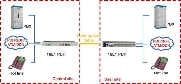
SNS Page


SOPTO Products
- Fiber Optic Transceiver Module
- High Speed Cable
- Fiber Optical Cable
- Fiber Optical Patch Cords
- Splitter CWDM DWDM
- PON Solution
- FTTH Box ODF Closure
- PCI-E Network Card
- Network Cables
- Fiber Optical Adapter
- Fiber Optical Attenuator
- Fiber Media Converter
- PDH Multiplexers
- Protocol Converter
- Digital Video Multiplexer
- Fiber Optical Tools
- Compatible
Related Products
Performance Feature
High integration desig
Low power consumption
Good EMC, EMI
Stable and Reliable
Multiplexer Knowledge
Recommended
4 x 1 Digital Multiplexer Designing Experiment
The aim of this experiment is to design and plot the characteristics of using pass transistor and transmission gate logic.
A multiplexer or mux is a combinational circuits that selects several analog or digital input signals and forwards the selected input into a single output line. A multiplexer of 2n inputs has n selected lines, are used to select which input line to send to the output.

Fig.1: The schematic diagram, boolean equation and the truth table of a 2:1 multiplexer with inputs A and B, select input S and the output Z.
Figure 2 shows how a 4:1 MUX can be constructed out of two 2:1 MUXs.
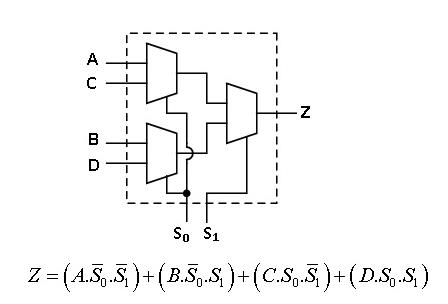
Fig.2.Implementation of 4:1 MUX using 2:1 MUXs
Design using pass-transistor logic
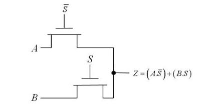
Fig.3. Design of a 2:1 MUX using pass-transistor logic
The pass-transistor logic attempts to reduce the number of transistors to implement a logic by allowing the primary inputs to drive gate terminals as well as source-drain terminals. The implementation of a 2:1 MUX requires 4 transistors (including the inverter required to invert S), while a complementary CMOS implementation would require 6 transistors. The reduced number of devices has the additional advantage of lower capacitance.
Design using transmission gate logic
A transmission gate is an electronic element and good non mechanical relay built with CMOS technology. It is made by parallel combination of nMOS and pMOS transistors with the input at the gate of one transistor (C) being complementary to the input at the gate () of the other. The symbol of a transmission gate is shown below in fig.4.
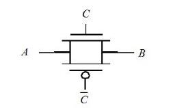
Fig.4: Symbol for transmission gate
The transmission gate acts as a bidirectional switch controlled by the gate signal C. When C=1, both MOSFETs are on, allowing the signal to pass through the gate. In short, A=B, if C=1. On the other hand, C=0, places both transistors in cut-off, creating an open circuit between nodes A and B. Fig.5 shows the implementation of a 2:1 MUX using transmission gate logic.
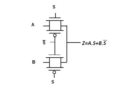
Fig.5: Circuit diagram of a 2:1 MUX using transmission gate logic
Here, the transmission gates select input A or B on the basis of the value of the control signal S. When S=0, Z=A and when S=1, Z=B.
For more info, please browse our website or contact a Sopto representative by calling 86-755-36946668, or by sending an email to info@sopto.com.