-

- Sopto Home
-

- Special Topic
-
- Twinax Cable Knowledge
-
- Point-to-Point vs. Structured Cabling in Data Center

Twinax Cable Knowledge
- Cable Labeling as Part of Data Center Management
- How to Correctly Run cables On Servers in a Data Center?
- 4 Realities You Should Consider 10G Ethernet for Your Business
- Is it finally the end of copper?
- Why We Need Both 40G and 100G Ethernet Cable?
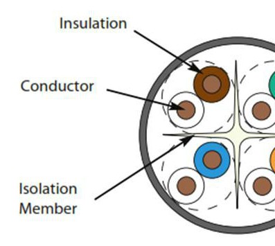
- What is Twisted Pair Cable?
- Benefits of Twisted Pair Cable Construction
- Why Copper Is Used in Cables?
- A Brief Look at Ethernet Cable Construction
SOPTO Special Topic
Certificate


Guarantee
Except products belongs to Bargain Shop section, all products are warranted by SOPTO only to purchasers for resale or for use in business or original equipment manufacturer, against defects in workmanship or materials under normal use (consumables, normal tear and wear excluded) for one year after date of purchase from SOPTO, unless otherwise stated...
Return Policies
Defective products will be accepted for exchange, at our discretion, within 14 days from receipt. Buyer might be requested to return the defective products to SOPTO for verification or authorized service location, as SOPTO designated, shipping costs prepaid. .....
Applications
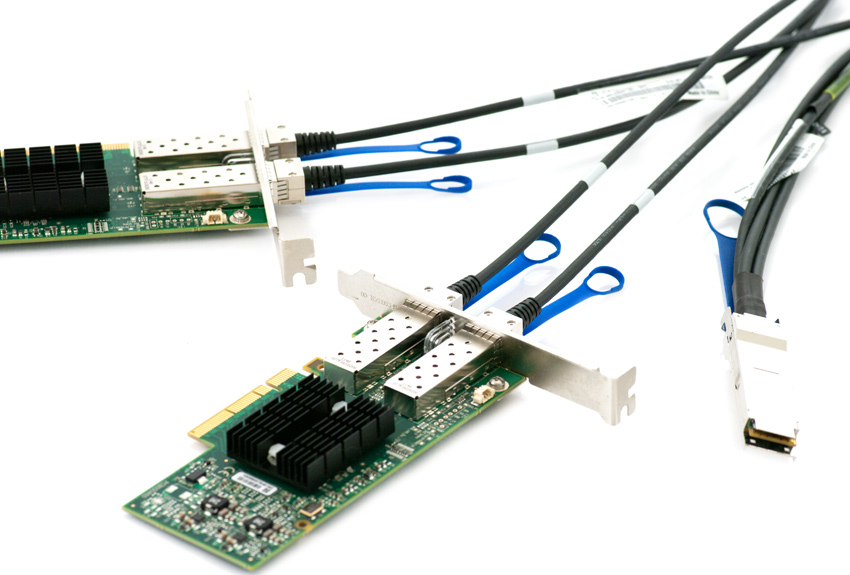 Twinax Cables are mainly used with PCI or PCI-E Card for the short distance interconnection in the server room.
SNS Page


SOPTO Products
- Fiber Optic Transceiver Module
- High Speed Cable
- Fiber Optical Cable
- Fiber Optical Patch Cords
- Splitter CWDM DWDM
- PON Solution
- FTTH Box ODF Closure
- PCI-E Network Card
- Network Cables
- Fiber Optical Adapter
- Fiber Optical Attenuator
- Fiber Media Converter
- PDH Multiplexers
- Protocol Converter
- Digital Video Multiplexer
- Fiber Optical Tools
- Compatible
Related Products
Performance Feature
Stable Transmission Speed
Reliable Transmission
Various Length Selection
Wider Operating Temperature
Good for HPC
Good for Data Center
Twinax Cable Knowledge
Recommended

Point-to-Point vs. Structured Cabling in Data Center
The old adage that history repeats itself is very true. If we don’t learn from history, we are doomed to repeat it. Many data centres today are victims of historical point-to-point cabling practices. Direct connections – “Point-to-Point” (i.e. from switches to servers, servers to storage, servers to other servers, etc.) are problematic and costly for a variety of reasons. In the best of data centre ecosystems, a standards-based structured cabling system will provide functionality and scalability with the maximum available options for current and future equipment. While Top of Rack (ToR) and End of Row (EoR) equipment mounting options are now available, these should supplement, not replace, a structured cabling system. ToR and EoR equipment placement both rely heavily on point to point cables, typically fibre jumpers and either twinax copper assemblies or stranded patch cords to connect the network or storage equipment ports to servers.
Data centres are evolving in a rather cyclical manner. When data centres (the original computer rooms) were first built, computing services were provided via a mainframe (virtualized) environment. End users’ dumb terminals were connected via point to point with coax or bus cabling using twinax. Enter the PC and Intel based server platforms, and new connections were needed. We have gone through several generations of possible cabling choices: coax (thicknet, thin net), category 3, 4, 5, 5e, 6. Now, the recommended 10 Gigabit capable copper choices for a data centre are category 6A, 7 and 7A channels, OM3 grade fibre for multimode capable electronics and single mode fibre for longer range electronics. In some data centres, samples of each of these systems can still be found under the raised floor or in overhead pathways, many of which originally were point-to-point. Today however, the “from” point and “to” point are a mystery, making cable abatement (removal of abandoned cable) problematic at best. Compounding this problem was a lack of naming conventions. If the cables were labeled at both ends, the labeling may not make sense anymore. For instance, a cable may be labeled “Unix Row, Cabinet 1.”
Years later, the Unix row may have been replaced and new personnel may not know where the Unix row was. There are two standards for structured cabling systems in a data centre: TIA 942 and draft ISO 24764, the latter of which is slated to publish in September, 2009.
These standards were created out of need. Both data centre standards have language stating that cabling should be installed to accommodate growth over the life of the data centre. Moves, adds and changes for a single or a few runs are expensive compared to the same channels run as part of an overall multi-channel installation project. For the larger projects, the end user realizes benefits from project pricing, economies of scale, and lower labor rates per channel. Single channels are typically more expensive, as it is more expensive to send personnel to run one channel. The risk of downtime increases with continual moves, adds and changes. Pathways and spaces can be properly planned and sized up front, but can become unruly and overfilled with additional channels being added on a regular basis.
Data centres that have issues with cable plant pathways typically suffer from poor planning. Growth and new channels were added out of need without regard to pathways. In some cases, pathways do not accommodate growth or maximum capacity over the life of the data centre. Overfilled pathways cause problems with airflow, and in some cases cabling becomes deformed due to the weight load, which can adversely affect transmission properties of the channel. This is particularly true in point-to-point systems that have grown into spaghetti-like conditions over time. Likewise, data centres have not practiced cable abatement or removal of old cabling as newer, higher performing systems are installed experience the same disheveled pathways.
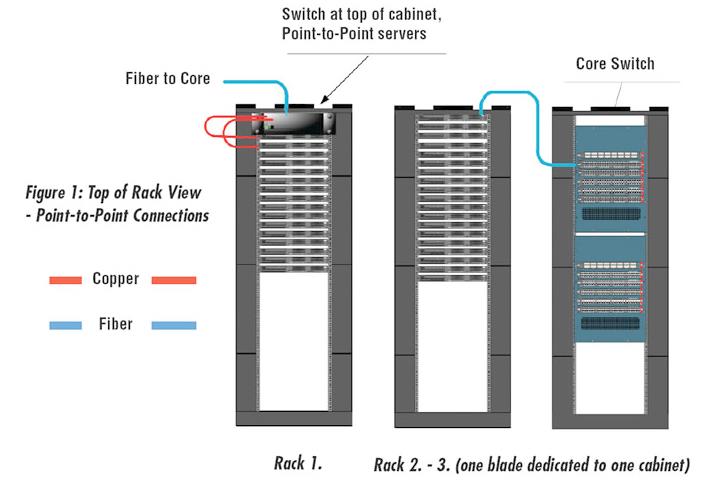
Figure1 Top of Rack View: Point to Point Connections
Figure1. depicts a ToR patching scenario between switch ports and servers without a structured cabling system. Rack 2 to Rack 3 connections are indicative of point-to-point server to-switch connections, also without a structured system. While proponents of these systems tout a decrease in cabling as a cost offset, further examination may negate such savings.
If a central KVM switch is used, the centralized structured cabling system would need to co-exist anyway, albeit with less channels day one. Newer electronics may have different channel minimum/maximum lengths resulting in the need for new channels. As electronics progress, the structured system may need to be added back to the data centre to support future equipment choices, completely negating the savings.
It will cost more to add the structured system later as pathways, spaces, and channels were not planned for and must be installed in a live environment increasing labor costs and the likelihood of downtime. When adding pathways and spaces, fire suppression systems and lighting may need to be moved to accommodate added overhead pathway systems. Floor voids may need to be increased and cabinets may need to be moved to allow new pathways to be routed in a non-obstructive manner for proper airflow.
Further examination highlights other disadvantages of ToR and Point-to-Point methodologies beyond the limitations outlined previously. In either the Rack 1 or Rack 2 -> Rack 3 scenario above, switch ports are dedicated to servers within a particular cabinet. This can lead to an oversubscription of ports. Suppose rack/cabinet 1 had the need for only 26 server connections for the entire rack. If a 48 ports switch (ToR switching) or 48 port blade (point-to-point server to switch) is dedicated to the cabinet, this means that 22 additional ports are purchased and maintenance is being paid on those unused ports.
A greater problem occurs when the full 48 ports are used. Adding even one new server will require the purchase of another 48 port switch. In this case, assuming two network connections for the new server, an oversubscription of 46 ports will be added to the cabinet. Even in an idle state, these excess ports consume power. Two power supplies are added to the cabinet. Active maintenance and warranty costs are also associated with the additional switch and ports.
Many of these ToR technologies have limitations for cabling length. Maximum lengths range from 2-15m and are more expensive than a structured cabling channel. Short channel lengths may limit locations of equipment within the shorter cable range. With a structured cabling system, 10GBASE-T can be supported up to 100 meters of category 6A, 7 and 7A cabling and allows more options for equipment placement within the data centre.
For more information, please browse our website or contact a Sopto representative by calling 86-755-36946668, or by sending an email to info@sopto.com.