

- Fiber Optic Transceiver Module
- High Speed Cable
- Fiber Optical Cable
- Fiber Optical Patch Cords
- Splitter CWDM DWDM
- PON Solution
- FTTH Box ODF Closure
- PCI-E Network Card
- Network Cables
- Fiber Optical Adapter
- Fiber Optical Attenuator
- Fiber Media Converter
- PDH Multiplexers
- Protocol Converter
- Digital Video Multiplexer
- Fiber Optical Tools
- Compatible

- Can SFP+120KM be available? ...
- Why the price has so huge di...
- Can XFP transceiver modules ...
- Must optical fiber jumper be...
- Is there a module which can ...
- Can different brands SFP tra...
- How long will you change you...
- The difference between DDM S...
- Comparison of EPON and GPON
- Should we use 3rd party’s ...
- How to make differences betw...
- What is Drop Cable?
- Comparison of CWDM and DWDM ...
- GEPON Technology
- Differences of OM1, OM2, OM3...
- What is the armored fiber op...
- What is DAC cable?
- How to Choose A Right Fusion...
- Why Using a Compatible SFP O...
- Optical fiber transmission l...

FBT splitter and PLC splitter
Part 1. Major differences between PLC splitters and Fused coupler (FBT coupler)
1. Technology behind FBT Coupler and PLC splitter.
FBT coupler: Fused biconical taper,this is traditional technology to weld several fiber together from side of the fiber.
PLC splitter:Planar waveguide is a micro-optical components products, the use of lithography, the semiconductor substrate in the medium or the formation of optical waveguide, to achieve branch distribution function.
2.Disadvantages and advantages between FBT and PLC.
| PLC splitter | FBT coupler (Fused) |
Split Ratio | 1*64 splits | 1*4 splits |
Eveness | Can split light evenly | Eveness is not very precise |
Size | Compact size | Big size for multi splits |
|
|
Part 2 Optical Performance
Study: Planar splitter (PLC splitter) vs Fused coupler (FBT coupler)
We use fiber optic splitter to distribute or combine optical signals in many applications,
we have one question:Shall I use PLC or Fused Coupler ?
When we do comparison, we need to do comparison for devices of the same split-ratio.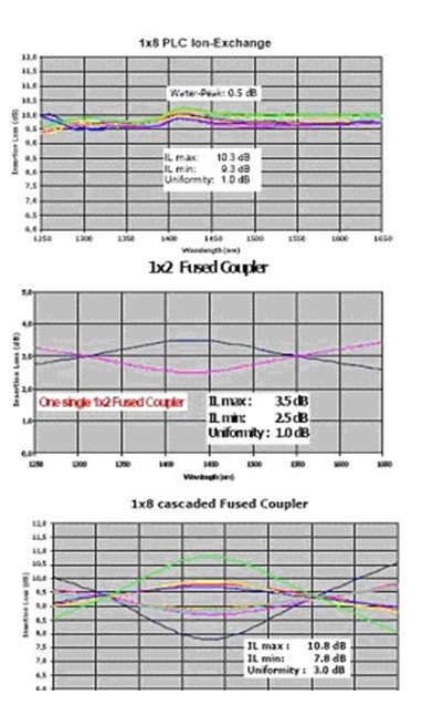
Optical Performance
Insertion loss and uniformity vs. wavelength
The figure 1 shows the insertion loss plot of a standard 1×8 PLC splitter from 1250 to 1650 nm. You can observe the maximum insertion loss including the water-peak in E band region(1360 to 1460 nm) and also the excellent uniformity out of this plot.
Typical value is 9.8dB for insertion loss and 0.5dB for uniformity.
A 1×2 fused coupler insertion loss plot is showed in the figure 2.if you analyze the operating wavelength range from 1250 to 1650 nm as for PLC splitter you will still find an overall good performance level. But that’s a single 1×2 fused coupler, so you are not comparing the same devices.
The 3rd plot represents the insertion loss spectral behavior for 1×8 fused coupler. To fabricate a 1×8 fused coupler device each arm have to be manufactured using 3 cascaded (spliced) 1×2 couplers. it means that the “worst” arm could show 10.8dB insertion loss max and the uniformity will be 3dB.
TDL (Temperature Dependent loss)
Due to the manufacturing process and to the sensitivity of the fused region and of the splices integrated in the device, Fused coupler manufacturers have to specify also the TDL value. for a 1×2 Fused coupler, a typical value is +/10.15dB for a temperature range from -5 to +75 centigrade . At the first sight, it could look good, but we have here again to take into account the cascading effect. To make the comparison with 1×8 PLC splitter we have to multiply 0.15 by 3 (3 1×2 for each arm) to finally obtain 0.45dB.
PLC splitter works from -40 to 85 centigrade with a typical TDL of out +/- 0.25dB (-5 to 75 centigrade:+/-0.15dB)
Please note that this TDL effect is already included in the Max. insertion loss specifications available on data sheets.
PDL (Polarization dependent loss)
An lon-exchange PLC splitter shows a PDL much less than 0.2 dB independently from the split-ratio. A 1×2 fused coupler PDL ranges from 0.1 to 0.15dB.Also in this case, we have to cascade discrete 1*2 Fused coupler to obtain the desired split-ratio, Then also PDL will be increased.
A 1×8 fused coupler will show up to 0.45dB PDL, what is more than the double of a 1×8 PLC splitter.
Reliability
As previously explained, to fabricate a 1×8 fused coupler, you need 7discrete 1×2 couplers and 6 splices. The risk of failure of a device, normally calculated by parameter called FIT(failure in time), is typically low for a single 1×2 fused coupler, but in the case of a 1×8 fuse fused coupler ,it has to be at lease multiplied by 7 and in addition to add the risk associated to the massive presence of splices in the circuits. As everybody knows, a splice is a potential failure point in a system to be minimized a s much as possible.
At the contrary, a PLC splitter knows only 2 critical points: input and output