- Fiber Optic Transceiver Module
- High Speed Cable
- Fiber Optical Cable
- Fiber Optical Patch Cords
- Splitter CWDM DWDM
- PON Solution
- FTTH Box ODF Closure
- PCI-E Network Card
- Network Cables
- Fiber Optical Adapter
- Fiber Optical Attenuator
- Fiber Media Converter
- PDH Multiplexers
- Protocol Converter
- Digital Video Multiplexer
- Fiber Optical Tools
- Compatible
- Can SFP+120KM be available? ...
- Why the price has so huge di...
- Can XFP transceiver modules ...
- Must optical fiber jumper be...
- Is there a module which can ...
- Can different brands SFP tra...
- How long will you change you...
- The difference between DDM S...
- Comparison of EPON and GPON
- Should we use 3rd party’s ...
- How to make differences betw...
- What is Drop Cable?
- Comparison of CWDM and DWDM ...
- GEPON Technology
- Differences of OM1, OM2, OM3...
- What is the armored fiber op...
- What is DAC cable?
- How to Choose A Right Fusion...
- Why Using a Compatible SFP O...
- Optical fiber transmission l...

Optical fiber transmission loss causes and solutions
A brief introduction of optical fiber transmission loss
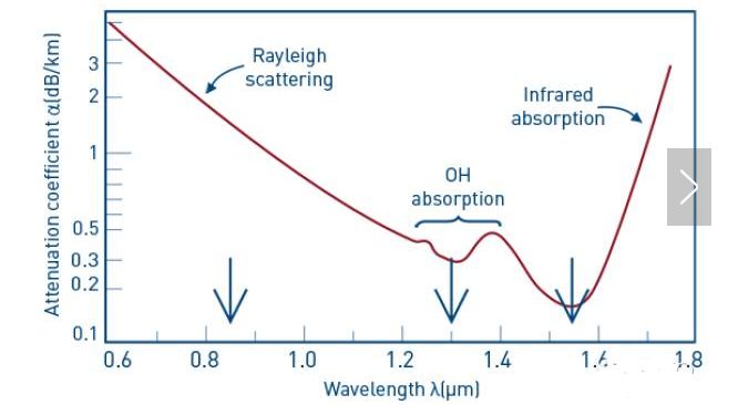
The optical fiber is a technology that uses glass as a waveguide to transmit information from one end to the other in the form of light. The inherent loss of fiber loss and the additional loss caused by the use of the fiber after its manufacture. Intrinsic loss, scattering loss and absorption loss are determined by the characteristics of the fiber optical cable material itself, and the inherent losses caused by different operating wavelengths are also different. The additional loss is artificially caused during the laying process of the optical fiber and can be avoided as far as possible. For example, the common end surface is not clean, it will cause additional loss, and even damage the equipment. In many cases, customers ignore the importance of fiber end face cleaning.

The transmission loss characteristic of the optical fiber is one of the most important factors that determine the transmission distance, transmission stability, and reliability of the optical network. Optical fiber transmission loss is caused by many reasons. In the construction and maintenance of optical fiber communication networks, the most noteworthy factors are the causes of transmission loss in optical fiber usage and how to reduce these losses. Let's talk about the continuation loss in the additional loss:
Connection loss and its solution

1.Continuation loss and its reason
(1) The inherent loss of the optical fiber is mainly due to the inconsistency of the mode field diameter of the optical fiber; the misalignment of the core diameter of the optical fiber; the cross-section of the core is not round; the concentricity between the core and the cladding is not good at four points; among them, the mode field diameter is the most inconsistent.
(2) Splicing loss splicing loss The extrinsic factor splicing loss is mainly caused by axial misalignment; axis (angle) inclination; end face separation (gap); fiber end face is incomplete; refractive index difference; fiber end face is not clean and subsequent personnel operation level, Operation steps, welding electrode cleaning degree, welding parameter setting, working environment cleanliness and other factors.
(3) Active Joint Loss The extrinsic joint loss due to extrinsic factors is mainly caused by poor quality of the movable connector, poor contact, uncleanness, and the same factors as the splice loss (such as axial misalignment, face gap, fold angle, refractive index difference, etc. ) Caused.

2.Connection loss solution
(1) Preparation of a complete optical fiber end face The preparation of the optical fiber end face is the most critical step in fiber optic connection. The perfection of the fiber end face is one of the important reasons that determine the fiber connection loss. The high-quality end faces should be smooth, free from burrs and defects, and should be perpendicular to the axis. The tilt angle of the optical fiber end face should be less than 0.3 degrees, present a smooth and smooth mirror surface, and be kept clean to avoid dust contamination. Should use the high-quality cutting knife, and use the cutting knife to cut fiber correctly. Bare fiber cleaning, cutting, and welding should be tightly connected, not too long intervals. Move the optical fiber gently and gently to prevent it from rubbing against other objects and damaging the end face of the optical fiber.
(2) Ensure that the connection environment meets the requirements. It is strictly forbidden to operate in dusty and humid environments. The joints, tools, and materials of the optical fiber cable should be kept clean. The optical fiber joints must not be wetted. The optical fiber to be cut must be clean and free of dirt. After cutting, the optical fiber must not be exposed to the air for too long, especially in dusty and damp environments. When the ambient temperature is too low, the necessary temperature-raising measures should be taken.
(3) Pick up experienced and well-trained continuation personnel for connection and testing. The level of continuation personnel will directly influence the size of the continuation loss. Continuing personnel should strictly follow the process of fiber fusion welding process to strictly control joint wear and tear, and be used during the welding process. The optical domain reflectometer (OTDR) monitors (continued losses ≤ 0.08dB/a) and should not be re-welded if it does not meet the requirements. When using an optical time domain reflectometer (OTDR), the loss of the joint should be measured from both directions, and the average of the two results should be obtained to eliminate the human factor error of the one-way OTDR measurement.
(4) The construction of optical fiber cable should be strictly in accordance with the regulations and requirements. When configuring the disk, try to make the entire disk configuration (single plate ≥ 500 meters) to minimize the number of joints. When laying, strictly according to the cables’ number and the order of the end of the deployment, so that the loss value to a minimum.
(5) Engineering design, construction and maintenance work should use the same batch of high-quality brand-name bare fiber as far as possible on a line of high-quality optical fiber with the same characteristics, in order to match the characteristics of the optical fiber as much as possible, so that the mode field diameter impact on the optical fiber splice loss Minimized.
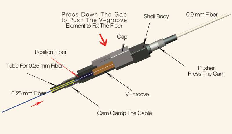
(6) Proper use of fusion splicer
① The fusion splicer should be operated correctly in strict accordance with the operating instructions and operating procedures of the fusion splicer.
②Place the fiber reasonably, and place the fiber in the V-groove of the fusion splicer. This is because for a single mode fiber with a core diameter of 10 nm, if the splice loss is less than 0.1 dB, the radial offset of the fiber axis is less than 0.8 nm.
③Set the welding parameters (predischarge current, time and main discharge current, main discharge time, etc.) correctly and reasonably according to the type of fiber.
④Remove the dust from the fusion splicer (in particular, the dust in the fixtures, mirrors, and v-grooves, and fiber slivers) in time of use and after use.
⑤ The life of the electrode of the fusion splicer is generally about 2,000 times. After a long time, the electrode will be oxidized, resulting in a large discharge current and an increase in the splice loss. At this point, the electrode can be removed, gently wiped with a cotton absorbent cotton swab, and then mounted on the fusion splicer, and the discharge is cleaned once. If the discharge current is still too large after multiple cleanings, the electrodes must be replaced.
(7) Ensure that the movable connector is clean
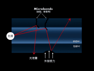
(8) The movable joint should be well connected and tightly coupled to prevent light leakage
(9) Try to use high-quality and qualified movable connectors to ensure that the performance indicators of the connectors comply with relevant regulations. The insertion loss of the active joints should be controlled at 0.3 dB/below (even lower), and the additional loss is not more than 0.2 dB/piece.
Conclusion
When we figure out the mechanism of loss, quantitatively analyze the magnitude of the loss caused by various factors, avoid the avoidance of loss and minimize it. This will have a great effect on the quality and speed of fiber transmission improving.


