
- Sopto Home
-

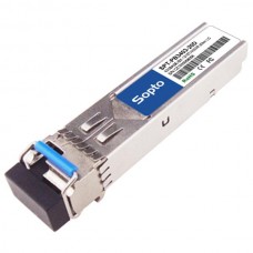
- SPT-PB3403-20(D) 20km 155Mbps SFP Bi-Directional Transceiver
- Fiber Optic Transceiver Module
- High Speed Cable
- Fiber Optical Cable
- Fiber Optical Patch Cords
- Splitter CWDM DWDM
- PON Solution
- FTTH Box ODF Closure
- PCI-E Network Card
- Network Cables
- Fiber Optical Adapter
- Fiber Optical Attenuator
- Fiber Media Converter
- PDH Multiplexers
- Protocol Converter
- Digital Video Multiplexer
- Fiber Optical Tools
- Compatible
SPT-PB3403-20(D) 20km 155Mbps SFP Bi-Directional Transceiver

SPT-PB3403-(L/S)20(D)
155Mbps SFP Bi-Directional Transceiver, 20km Reach 1310nm TX / 1490 nm RX
Features
- Up to 155Mbps data-rate
- 1310nm FP laser and PIN photo detector for 20km transmission
- Compliant with SFP MSA and SFF-8472 with simplex LC(SC)receptacle
- Digital Diagnostic Monitoring: Internal Calibration or External Calibration
- Compatible with RoHS
- +3.3V single power supply
-
Operating case temperature:
Standard: 0 to +70°C
Applications
- SDH STM-1, S-1.1,L-1.1, L-1.2
- SONET OC-3 IR1, LR1, LR2
- Other optical links
Description
The SFP-BIDI transceivers are high performance, cost effective modules supporting data-rate of 155Mbps and 20km transmission distance with SMF.
The transceiver consists of three sections: a FP laser transmitter, a PIN photodiode integrated with a trans-impedance preamplifier (TIA) and MCU control unit. All modules satisfy class I laser safety requirements.
The transceivers are compatible with SFP Multi-Source Agreement (MSA) and SFF-8472. For further information, please refer to SFP MSA.
.jpg)
Absolute Maximum Ratings
|
Parameter |
Symbol |
Min |
Max |
Unit |
|
Supply Voltage |
Vcc |
-0.5 |
4.5 |
V |
|
Storage Temperature |
Ts |
-40 |
+85 |
°C |
|
Operating Humidity |
- |
5 |
85 |
% |
Recommended Operating Conditions
|
Parameter |
Symbol |
Min |
Typical |
Max |
Unit |
|
|
Operating Case Temperature |
Standard |
Tc |
0 |
|
+70 |
°C |
|
Power Supply Voltage |
Vcc |
3.13 |
3.3 |
3.47 |
V |
|
|
Power Supply Current |
Icc |
|
|
300 |
mA |
|
|
Data Rate |
|
|
155 |
|
Mbps |
|
Optical and Electrical Characteristics
SPT-PB3403-(L/S)20(D): (FP and PIN, 1310nm, 20km Reach)
|
Parameter |
Symbol |
Min |
Typical |
Max |
Unit |
Notes |
||
|
Transmitter |
||||||||
|
Centre Wavelength |
λc |
1260 |
1310 |
1360 |
nm |
|
||
|
Spectral Width(RMS) |
∆λ |
|
|
4 |
nm |
|
||
|
AverageOutputPower |
Pout |
-14 |
|
-8 |
dBm |
1 |
||
|
Extinction Ratio |
ER |
9 |
|
|
dB |
|
||
|
Data Input Swing Differential |
VIN |
400 |
|
1800 |
mV |
2 |
||
|
InputDifferentialImpedance |
ZIN |
90 |
100 |
110 |
Ω |
|
||
|
TX Disable |
Disable |
|
2.0 |
|
Vcc |
V |
|
|
|
Enable |
|
0 |
|
0.8 |
V |
|
||
|
TX Fault |
Fault |
|
2.0 |
|
Vcc |
V |
|
|
|
Normal |
|
0 |
|
0.8 |
V |
|
||
|
Receiver |
||||||||
|
Centre Wavelength |
λc |
1470 |
|
1510 |
nm |
|
||
|
Receiver Sensitivity |
|
|
|
-32 |
dBm |
3 |
||
|
Receiver Overload |
|
-3 |
|
|
dBm |
3 |
||
|
LOS De-Assert |
LOSD |
|
|
-32 |
dBm |
|
||
|
LOS Assert |
LOSA |
-40 |
|
|
dBm |
|
||
|
LOS Hysteresis |
|
1 |
|
4 |
dB |
|
||
|
Data Output Swing Differential |
Vout |
400 |
|
1800 |
mV |
4 |
||
|
LOS |
High |
2.0 |
|
Vcc |
V |
|
||
|
Low |
|
|
0.8 |
V |
|
|||
Notes:
1. The optical power is launched into SMF.
2. PECL input, internally AC-coupled and terminated.
3. Measured with a PRBS 223-1 test pattern @155Mbps, BER ≤1×10⁻¹⁰.
4. Internally AC-coupled.
Timing and Electrical
|
Parameter |
Symbol |
Min |
Typical |
Max |
Unit |
|
Tx Disable Negate Time |
t_on |
|
|
1 |
ms |
|
Tx Disable Assert Time |
t_off |
|
|
10 |
µs |
|
Time To Initialize, Including Reset of Tx Fault |
t_init |
|
|
300 |
ms |
|
Tx Fault Assert Time |
t_fault |
|
|
100 |
µs |
|
Tx Disable To Reset |
t_reset |
10 |
|
|
µs |
|
LOS Assert Time |
t_loss_on |
|
|
100 |
µs |
|
LOS De-assert Time |
t_loss_off |
|
|
100 |
µs |
|
Serial ID Clock Rate |
f_serial_clock |
|
|
400 |
KHz |
|
MOD_DEF(0:2)-High |
VH |
2 |
|
Vcc |
V |
|
MOD_DEF(0:2)-Low |
VL |
|
|
0.8 |
V |
Diagnostics
|
Parameter |
Range |
Unit |
Accuracy |
Calibration |
|
Temperature |
0 to +70 |
°C |
±3°C |
Internal/External |
|
Voltage |
3.0 to 3.6 |
V |
±3% |
Internal/External |
|
Bias Current |
0 to 100 |
mA |
±10% |
Internal/External |
|
TX Power |
-14 to -8 |
dBm |
±3dB |
Internal/External |
|
RX Power |
-28 to -3 |
dBm |
±3dB |
Internal/External |
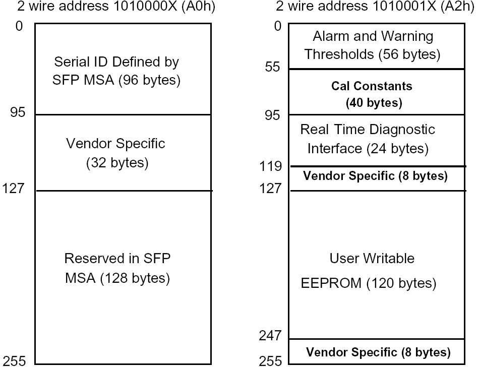
Digital Diagnostic Memory Map
The transceivers provide serial ID memory contents and diagnostic information about the present operating conditions by the 2-wire serial interface (SCL, SDA).
The diagnostic information with internal calibration or external calibration all are implemented, including received power monitoring, transmitted power monitoring, bias current monitoring, supply voltage monitoring and temperature monitoring.
The digital diagnostic memory map specific data field defines as following.
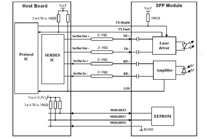
Recommended Interface Circuit
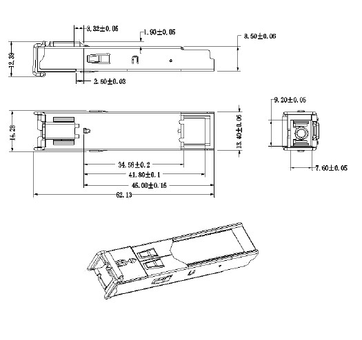
Mechanical Dimensions
A. LC Connector
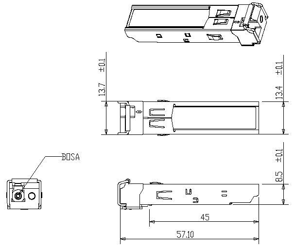
B.SC Connector
Ordering Information
|
Part Number |
Product Description |
|
|
SPT-PB3403-S20 |
1310nm, 155Mbps, SC, 20km, 0°C~+70°C |
|
|
SPT-PB3403-S20D |
1310nm, 155Mbps, SC, 20km, 0°C~+70°C, With Digital Diagnostic Monitoring |
|
|
SPT-PB3403-L20 |
1310nm, 155Mbps, LC, 20km, 0°C~+70°C |
|
|
SPT-PB3403-L20D |
1310nm, 155Mbps, LC, 20km, 0°C~+70°C,With Digital Diagnostic Monitoring |
|
E-mail:sales@sopto.com