
- Sopto Home
-

- 10G 1330/1270nm 60km BIDI SFP+ 60km Transceiver SPT-PB3327TG-L60D
- Fiber Optic Transceiver Module
- High Speed Cable
- Fiber Optical Cable
- Fiber Optical Patch Cords
- Splitter CWDM DWDM
- PON Solution
- FTTH Box ODF Closure
- PCI-E Network Card
- Network Cables
- Fiber Optical Adapter
- Fiber Optical Attenuator
- Fiber Media Converter
- PDH Multiplexers
- Protocol Converter
- Digital Video Multiplexer
- Fiber Optical Tools
- Compatible
10G 1330/1270nm 60km BIDI SFP+ 60km Transceiver SPT-PB3327TG-L60D

PRODUCT FEATURES
- Up to 10.7Gbps Data Links
- Single Mode LC Receptacle Bi-directional Transceiver
- Up to 60km transmission on SMF
- Power dissipation<1.5W
- 1330nm DFB laser and APD receiver
- 2-wire interface with integrated Digital Diagnostic monitoring
- EEPROM with Serial ID Functionality
- Compliant with FC_PI_4 REV 7.0
- Compliant with SFP+ MSA with duplex LC connector
- Single + 3.3V Power Supply
- Case operating temperature: -5ºC~+70ºC
APPLICATIONS
- 10GBASE-BX at 10.3125 Gb/s
- 10GBASE-BX at 9.953 Gb/s
- 1000 Base-LX Ethernet
- 8XFC at 8.5Gbps
- 4XFC at 4.25Gpbs
- 2XFC at 2.125Gpbs
- 1xFC at 1.0625Gbps
STANDARD
- Compliant with SFF-8472 SFP+ MSA.
- Compliant with FC_PI_4 REV 7.0.
- Compliant to SFP+ SFF-8431 and SFF-8432.
- RoHS Compliant.
PRODUCT DESCRIPTION
SPT-PB3327TG-L60D is hot pluggable 3.3V Small-Form-Factor transceiver module. It designed expressly for high-speed communication applications that require rates up to 10.7Gb/s,it designed to be compliant with SFF-8472 SFP+ MSA. The module data link up to 60km in 9/125um single mode fiber. The optical output can be disabled by a LVTTL logic high-level input of Tx Disable. Tx Fault is provided to indicate that degradation of the laser. Loss of signal (LOS) output is provided to indicate the loss of an input optical signal of receiver or the link status with partner.
Ⅰ Absolute Maximum Ratings
|
Parameter |
Symbol |
Min. |
Typ. |
Max. |
Unit |
Note |
|
Storage Temperature |
Ts |
-40 |
- |
85 |
ºC |
|
|
Storage Ambient Humidity |
HA |
5 |
- |
95 |
% |
|
|
Operating Relative Humidity |
RH |
- |
- |
85 |
% |
|
|
Power Supply Voltage |
VCC |
-0.3 |
- |
4 |
V |
|
|
Signal Input Voltage |
|
Vcc-0.3 |
- |
Vcc+0.3 |
V |
|
Ⅱ Recommended Operating Conditions
|
Parameter |
Symbol |
Min. |
Typ. |
Max. |
Unit |
Note |
|
Case Operating Temperature |
Tcase |
-5 |
- |
70 |
ºC |
Without air flow |
|
Power Supply Voltage |
VCC |
3.14 |
3.3 |
3.47 |
V |
|
|
Power Supply Current |
ICC |
- |
300 |
450 |
mA |
|
|
Data Rate |
BR |
|
10.3125 |
|
Gbps |
|
|
Transmission Distance |
TD |
|
- |
60 |
km |
Note (1) |
|
Coupled fiber |
Single mode fiber |
ITU-T G.652 |
||||
Ⅲ Optical Characteristics
|
Parameter |
Symbol |
Min. |
Typ. |
Max. |
Unit |
Note |
|
Transmitter |
||||||
|
Average Launched Power |
PO |
1 |
- |
5 |
dBm |
|
|
Average Launched Power(Laser Off) |
Poff |
- |
- |
-40 |
dBm |
Note (1) |
|
Center Wavelength Range |
λC |
1320 |
1330 |
1340 |
nm |
|
|
Side mode suppression ratio |
SMSR |
30 |
- |
- |
dB |
|
|
Spectrum Bandwidth(-20dB) |
σ |
- |
- |
1 |
nm |
|
|
Extinction Ratio |
ER |
3.5 |
|
- |
dB |
Note (2) |
|
Output Eye Mask |
Compliant with FC_PI_4 REV 7.0 |
|
Note (2) |
|||
|
Receiver |
||||||
|
Input Optical Wavelength |
λIN |
1260 |
|
1280 |
nm |
|
|
Receiver Sensitivity |
Psen |
- |
- |
-20 |
dBm |
Note (3) |
|
Input Saturation Power (Overload) |
PSAT |
-6 |
- |
- |
dBm |
Note (3) |
|
LOS -Assert Power |
PA |
-35 |
- |
- |
dBm |
|
|
LOS -Deassert Power |
PD |
- |
- |
-21 |
dBm |
|
|
LOS -Hysteresis |
PHys |
0.5 |
- |
5 |
dB |
|
- The optical power is launched into SMF
- Measured with RPBS 2 31-1 test pattern @10.3125Gbs
- Measured with RPBS 2 31-1 test pattern @10.3125Gbs BER=<10 -12
- Electrical Interface Characteristics
|
Parameter |
Symbol |
Min. |
Typ. |
Max. |
Unit |
Note |
|
Total power supply current |
Icc |
- |
300- |
450 |
mA |
|
|
Transmitter |
||||||
|
Differential Data Input Voltage |
VDT |
180 |
- |
700 |
mVp-p |
|
|
Differential line input Impedance |
RIN |
85 |
100 |
115 |
Ohm |
|
|
Transmitter Fault Output-High |
VFaultH |
2.4 |
- |
Vcc |
V |
|
|
Transmitter Fault Output-Low |
VFaultL |
-0.3 |
- |
0.8 |
V |
|
|
Transmitter Disable Voltage- High |
VDisH |
2 |
- |
Vcc+0.3 |
V |
|
|
Transmitter Disable Voltage- low |
VDisL |
-0.3 |
- |
0.8 |
V |
|
|
Receiver |
||||||
|
Differential Data Output Voltage |
VDR |
300 |
- |
850 |
mVp-p |
|
|
Differential line Output Impedance |
ROUT |
80 |
100 |
120 |
Ohm |
|
|
Receiver LOS Pull up Resistor |
RLOS |
4.7 |
- |
10 |
KOhm |
|
|
Data Output Rise/Fall time |
tr/tf |
|
- |
38 |
ps |
|
|
LOS Output Voltage-High |
VLOSH |
2 |
- |
Vcc |
V |
|
|
LOS Output Voltage-Low |
VLOSL |
-0.3 |
- |
0.4 |
V |
|
- Pin Description
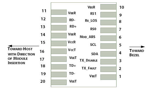
Diagram of Host Board Connector Block Pin Numbers and Name
|
Pin |
Symbol |
Name/Description |
Ref. |
|
1 |
VEET |
Transmitter Ground (Common with Receiver Ground) |
1 |
|
2 |
TFAULT |
Transmitter Fault. |
2 |
|
3 |
TDIS |
Transmitter Disable. Laser output disabled on high or open. |
3 |
|
4 |
SDA |
2-wire Serial Interface Data Line |
4 |
|
5 |
SCL |
2-wire Serial Interface Clock Line |
4 |
|
6 |
MOD_ABS |
Module Absent. Grounded within the module |
4 |
|
7 |
RS0 |
Rate Select 0 |
5 |
|
8 |
LOS |
Loss of Signal indication. Logic 0 indicates normal operation. |
6 |
|
9 |
RS1 |
No connection required |
1 |
|
10 |
VEER |
Receiver Ground (Common with Transmitter Ground) |
1 |
|
11 |
VEER |
Receiver Ground (Common with Transmitter Ground) |
1 |
|
12 |
RD- |
Receiver Inverted DATA out. AC Coupled |
|
|
13 |
RD+ |
Receiver Non-inverted DATA out. AC Coupled |
|
|
14 |
VEER |
Receiver Ground (Common with Transmitter Ground) |
1 |
|
15 |
VCCR |
Receiver Power Supply |
|
|
16 |
VCCT |
Transmitter Power Supply |
|
|
17 |
VEET |
Transmitter Ground (Common with Receiver Ground) |
1 |
|
18 |
TD+ |
Transmitter Non-Inverted DATA in. AC Coupled. |
|
|
19 |
TD- |
Transmitter Inverted DATA in. AC Coupled. |
|
|
20 |
VEET |
Transmitter Ground (Common with Receiver Ground) |
1 |
- Circuit ground is internally isolated from chassis ground.
- TFAULTis an open collector/drain output, which should be pulled up with a 4.7k – 10k Ohms resistor on the host board if intended for use. Pull up voltage should be between 2.0V to Vcc + 0.3V.A high output indicates a transmitter fault caused by either the TX bias current or the TX output power exceeding the preset alarm thresholds. A low output indicates normal operation. In the low state, the output is pulled to <0.8V.
- Laser output disabled on TDIS>2.0V or open, enabled on TDIS<0.8V.
- Should be pulled up with 4.7kΩ- 10kΩ host board to a voltage between 2.0V and 3.6V. MOD_ABS pulls line low to indicate module is plugged in.
- Internally pulled down per SFF-8431 Rev 4.1.
- LOS is open collector output. It should be pulled up with 4.7kΩ – 10kΩ on host board to a voltage between 2.0V and 3.6V. Logic 0 indicates normal operation; logic 1 indicates loss of signal.
- Recommended Interface Circuit
.jpg)
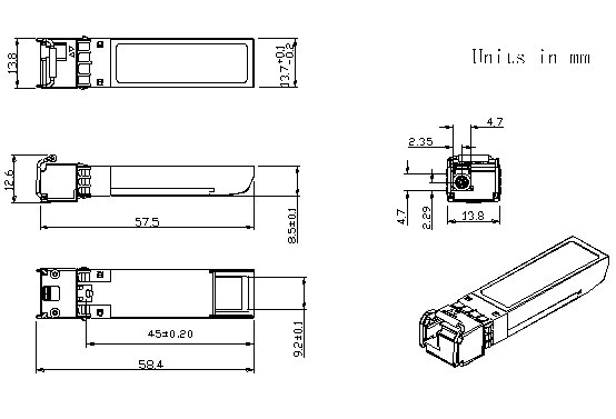
- Outline Dimensions
Appendix A. Document Revision
|
Version No. |
Date |
Description |
|
1.0 |
2011-11-10 |
Preliminary datasheet |
E-mail: sales@sopto.com
Web : http://www.sopto.com