
- Sopto Home
-

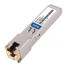
- 100M Copper SFP Transceiver SPT-PE-T4
- Fiber Optic Transceiver Module
- High Speed Cable
- Fiber Optical Cable
- Fiber Optical Patch Cords
- Splitter CWDM DWDM
- PON Solution
- FTTH Box ODF Closure
- PCI-E Network Card
- Network Cables
- Fiber Optical Adapter
- Fiber Optical Attenuator
- Fiber Media Converter
- PDH Multiplexers
- Protocol Converter
- Digital Video Multiplexer
- Fiber Optical Tools
- Compatible
100M Copper SFP Transceiver SPT-PE-T4

Features
- Hot-pluggable SFP footprint
- Extended case temperature range (0°C to +70°C )
- Fully metallic enclosure for low EMI
- Compact RJ-45 connector assembly
- It supports RX_LOS(Loss of Signal) function
- Compatible with IEEE802.3u
- Access to physical layer IC via 2-wire serial bus
- A 10/100BASE-TX/ 100BASE-FX converter
Applications
- This 100Base-TX Copper SFP Transceiver supports the SFP based switch100Base-FX ports that accept standard 100Base-FX optics SFP.
Description
SPT-PE-T4 Copper Small Form Pluggable (SFP) transceiver module is specifically designed for converting 100Base-FX NRZI port interface to 10/100Base-TX interface with RJ45 connector. The transceiver module is compliant with the SFP MultiSource Agreement (MSA) and IEEE802.3u. With the hot plug ability, the module offers a flexible and easy way to be installed into SFP MSA compliant ports at any time without the interruption of the host equipments operating online.
The Copper SFP transceivers use an integrated RJ-45 connector with transformer and PHY IC.
Pin Definitions
Pin Diagram
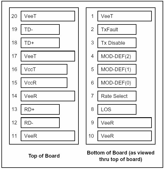
Pin Descriptions
|
Pin |
Signal Name |
Description |
Plug Seq. |
Notes |
|
1 |
VEET |
Transmitter Ground |
1 |
|
|
2 |
TX FAULT |
Transmitter Fault Indication |
3 |
Note1 |
|
3 |
TX DISABLE |
Transmitter Disable |
3 |
Note2 |
|
4 |
MOD_DEF(2) |
SDA Serial Data Signal |
3 |
Note3 |
|
5 |
MOD_DEF(1) |
SCL Serial Clock Signal |
3 |
Note3 |
|
6 |
MOD_DEF(0) |
TTL Low |
3 |
Note3 |
|
7 |
Rate Select |
Not Connected |
3 |
|
|
8 |
LOS |
Loss of Signal |
3 |
Note 4 |
|
9 |
VEER |
Receiver ground |
1 |
|
|
10 |
VEER |
Receiver ground |
1 |
|
|
11 |
VEER |
Receiver ground |
1 |
|
|
12 |
RX- |
Inv. Received Data Out |
3 |
Note 5 |
|
13 |
RX+ |
Received Data Out |
3 |
Note 5 |
|
14 |
VEER |
Receiver ground |
1 |
|
|
15 |
VCCR |
Receiver Power Supply |
2 |
|
|
16 |
VCCT |
Transmitter Power Supply |
2 |
|
|
17 |
VEET |
Transmitter Ground |
1 |
|
|
18 |
TX+ |
Transmit Data In |
3 |
Note 6 |
|
19 |
TX- |
Inv. Transmit Data In |
3 |
Note 6 |
|
20 |
VEET |
Transmitter Ground |
1 |
|
Notes:
Plug Seq.: Pin engagement sequence during hot plugging.
1) TX Fault is not supported and is always connected to ground.
2) TX Disable is an input that is used to shut down the transmitter optical output. It is pulled up within the module with a 4.7 ¨C 10 K resistor. Its states are:
Low (0 to 0.8V): Transmitter on
(>0.8, < 2.0V): Undefined
High (2.0 to 3.465V): Transmitter Disabled
Open: Transmitter Disabled
3) Mod-Def 0,1,2. These are the module definition pins. They should be pulled up with a 4.7K to 10K resistor on the host board. The pull-up voltage shall be VccT or VccR
Mod-Def 0 is grounded by the module to indicate that the module is present
Mod-Def 1 is the clock line of two wire serial interface for serial ID
Mod-Def 2 is the data line of two wire serial interface for serial ID
4) LOS is an open collector output, which should be pulled up with a 4.7k~10kΩ resistor. Pull up voltage between 2.0V and Vcc+0.3V. Logic 1 indicates loss of signal; Logic 0 indicates normal operation. In the low state, the output will be pulled to less than 0.8V.
5) RD-/+: These are the differential receiver outputs. They are AC-coupled, differential lines with 100 differential termination inside the module.
6) TD-/+: These are the differential transmitter inputs. They are AC-coupled, differential lines with 100 differential termination inside the module.
+3.3V Volt Electrical Power Interface
The SPT-PE-T4 has an input voltage range of +3.3V +/- 5%. The 3.3V maximum voltage is not allowed for continuous operation.
Table 1. +3.3V Volt electrical power interface
|
+3.3V volt Electrical Power Interface |
||||||
|
Parameter |
Symbol |
Min |
Typ |
Max |
Units |
Notes/Conditions |
|
Supply Current |
Is |
|
320 |
375 |
mA |
1.2W max power over full range of voltage and temperature.See caution note below |
|
Input Voltage |
Vcc |
3.13 |
3.3 |
3.47 |
V |
Referenced to GND |
|
Maximum Voltage |
Vmax |
|
|
4 |
V |
|
|
Surge Current |
Isurge |
|
|
30 |
mA |
Hot plug above steady state current. See caution note below |
Caution: Power consumption and surge current are higher than the specified values in the SFP MSA
Low-Speed Signals
MOD_DEF(1) (SCL) and MOD_DEF(2) (SDA), are open drain CMOS signals (see section VII, “Serial Communication Protocol”). Both MOD_DEF(1) and MOD_DEF(2) must be pulled up to host_Vcc.
Table 2. Low-speed signals, electronic characteristics
|
Low-Speed Signals, Electronic Characteristics |
|||||
|
Parameter |
Symbol |
Min |
Max |
Units |
Notes/Conditions |
|
SFP Output LOW |
VOL |
0 |
0.5 |
V |
4.7k to 10k pull-up to host_Vcc, measured at host side of connector |
|
SFP Output HIGH |
VOH |
host_Vcc - 0.5 |
host_Vcc + 0.3 |
V |
4.7k to 10k pull-up to host_Vcc, measured at host side of connector |
|
SFP Input LOW |
VIL |
0 |
0.8 |
V |
4.7k to 10k pull-up to Vcc, measured at SFP side of connector |
|
SFP Input HIGH |
VIH |
2 |
Vcc + 0.3 |
V |
4.7k to 10k pull-up to Vcc, measured at SFP side of connector |
High-Speed Electrical Interface
All high-speed signals are AC-coupled internally.
Table 3. High-speed electrical interface, transmission line-SFP
|
High-Speed Electrical Interface Transmission Line-SFP |
||||||
|
Parameter |
Symbol |
Min |
Typ |
Max |
Units |
Notes/Conditions |
|
Line Frequency |
fL |
|
125 |
|
MHz |
5-level encoding, per IEEE 802.3u |
|
Tx Output Impedance |
Zout,TX |
|
100 |
|
Ohm |
Differential, for all Frequencies between 1MHz and 125MHz |
|
Rx Input Impedance |
Zin,RX |
|
100 |
|
Ohm |
Differential, for all Frequencies between 1MHz and 125MHz |
High-speed electrical interface, host-SFP
Table 4. High-speed electrical interface, host-SFP
|
High-Speed Electrical Interface, Host-SFP |
||||||
|
Parameter |
Symbol |
Min |
Typ |
Max |
Units |
Notes/Conditions |
|
Single ended data input swing |
Vinsing |
250 |
|
1200 |
mV |
Single ended |
|
Single ended data output swing |
Voutsing |
350 |
|
800 |
mV |
Single ended |
|
Rise/Fall Time |
Tr,Tf |
|
175 |
|
psec |
20%-80% |
|
Tx Input Impedance |
Zin |
|
50 |
|
Ohm |
Single ended |
|
Rx Output Impedance |
Zout |
|
50 |
|
Ohm |
Single ended |
General Specifications
Table 5. General specifications
|
General |
||||||
|
Parameter |
Symbol |
Min |
Typ |
Max |
Units |
Notes/Conditions |
|
Data Rate |
BR |
10 |
|
100 |
Mb/sec |
IEEE802.3u |
|
Cable Length |
L |
|
|
100 |
m |
Category 5 UTP. BER <10-12 |
Notes:
1. Clock tolerance is +/- 50 ppm
2. By default, the GE-FB-PXRC is a full duplex device in preferred master mode
3. Automatic crossover detection is enabled. External crossover cable is not required
Environmental Specifications
Table 6. Environmental specifications
|
Environmental Specifications |
||||||
|
Parameter |
Symbol |
Min |
Typ |
Max |
Units |
Notes/Conditions |
|
Operating Temperature |
Top |
0 |
|
70 |
°C |
Case temperature |
|
Storage Temperature |
Tsto |
-40 |
|
85 |
°C |
Ambient temperature |
Mechanical Specifications
The host-side of the GE-FB-PXRC conforms to the mechanical specifications outlined in the SFP MSA1. The front portion of the SFP (part extending beyond the face plate of the host) is larger to accommodate the RJ-45 connector.
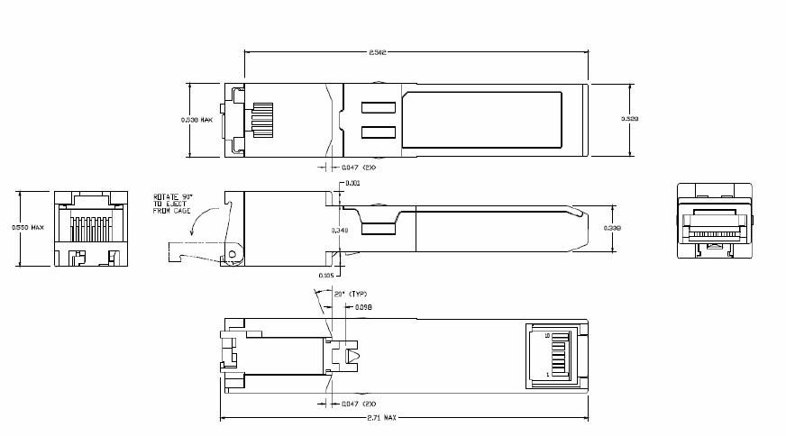
Figure 2. SPT-PE-T4 mechanical dimensions
Ordering information
|
Part number |
Operating Case temperature |
|
SPT-PE-T4 |
10/100Mbps, Copper SFP with spring latch |
|
SPT-PE-T4 |
100Mbps only, Copper SFP with spring latch |
E-mail: sales@sopto.com
Web : http://www.sopto.com